


A-2
Cisco MGX 8950 Hardware Installation Guide
Release 3, Part Number 78-14147-02 Rev. A0, November 2002
Appendix A Technical Specifications
AXSM Specifications
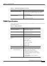
AXSM Specifications
Table A-2 lists the physical specifications for the AXSMs.
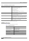
Shipping weight for individual components Front and back cards: 6.0 lb (2.73 kg) per card set
Card cage with cards: 160 lb (72.73 kg)
Exhaust plenum: 8 lb (3.63 kg)
Fan tray: 9.5 lb (4.3 kg)
Air intake plenum: 8 lb (3.63 kg)
AC power supply tray with power supplies: 45 lb (20.41 kg)
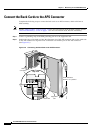
APS connector: 1 lb (0.45 kg)
Clearance requirement for the enclosure Minimum 30 in. front and rear; 12 in. side clearance recommended
Power input voltage • AC source
2
: Normal operating range is 200–240 VAC, 47 to 63 Hz.
The maximum voltage range is 180–254 VAC.
• DC source: –42 to –56 VDC.
AC system current requirements Configuration-dependent: Use Table 2-5 for exact requirements. For
general planning purposes: 14.4 A at a nominal voltage of 200 VAC. At
the minimum voltage limit of 180 VAC, the current draw is a maximum
of 21 A.
DC system current requirements Configuration-dependent: Use Table 2-5 for exact requirements. For
general planning purposes: 76 A (37.5 A per feed) at nominal -48 VDC;
86 A (43 A per feed) at -42 VDC minimum.
1. RUs = rack units
2. The AC power source must be within 6 feet (1.8 meters) of the system and easily accessible.
Table A-1 Cisco MGX 8950 System Specifications (continued)
Specification Description
Ta b l e A-2 AXSM Physical Specifications
Specification Description
Dimensions for AXSMs Height: 15.65 in. (39.75 cm)
Depth: 16.25 in. (41.28 cm)
Dimensions for back cards Height: 7.00 in. (17.78 cm)
Depth: 4.50 in. (11.43 cm)
Weight for AXSMs 1.74 lb (0.789 kg)
Weight for back cards Varies with the back card
External interfaces 1 to 16 (no connectors on the double-height service module)
Power –48 VDC
Maximum power consumption See Table 2-5