


3-37
Cisco MGX 8950 Hardware Installation Guide
Release 3, Part Number 78-14147-02 Rev. A0, November 2002
Chapter 3 Installing a Cisco MGX 8950
Installation Procedures
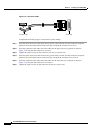
Caution Do NOT use power tools for this procedure.
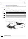
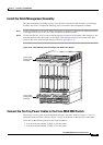
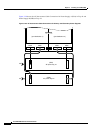
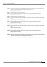
Step 1 Insert the connector labeled “Card Cage A1” into the card cage receptacle labeled “PSA 1.”
Step 2 Push the connector in to seat it.
Step 3 Tighten the captive screws firmly by hand.
Step 4 Insert the other end of the cable labeled “PS Tray 1 J1” into the primary (top) AC power tray receptacle
labeled “J1.”
Step 5 Push the connector in to seat it.
Step 6 Tighten the captive screws firmly by hand.
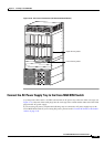
Step 7 Insert the connector labeled “Card Cage B1” into the card cage receptacle labeled “PSB 1.”
Push the connector in to seat it.
Step 8 Tighten the captive screws firmly by hand.
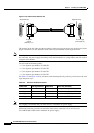
Step 9 Insert the other end of the cable labeled “PS Tray 2 J1” into the secondary (bottom) AC power tray
receptacle labeled “J1.”
Step 10 Tighten the captive screws firmly by hand.
Step 11 Insert the connector labeled “Card Cage B2” into the card cage receptacle labeled “PSB 2.”
Push the connector in to seat it.
Step 12 Tighten the captive screws firmly by hand.
Step 13 Insert the other end of the cable labeled “PS Tray 2 J2” into the secondary AC power tray receptacle
labeled “J2.”
Push the connector in to seat it.
Step 14 Tighten the captive screws firmly by hand.
Step 15 Insert the connector labeled “Card Cage A2” into the card cage receptacle labeled “PSA 2.”
Push the connector in to seat it.
Step 16 Tighten the captive screws firmly by hand.
Step 17 Insert the other end of the cable labeled “PS Tray 1 J2” into the primary AC power tray receptacle labeled
“J2.”