


4-7
Cisco MGX 8950 Hardware Installation Guide
Release 3, Part Number 78-14147-02 Rev. A0, November 2002
Chapter 4 Maintaining the Cisco MGX 8950 Switch
Remove and Install the Single-Height Front Cards
Remove and Install the Single-Height Front Cards
The following sections describe how to remove and install a single-height front card.
Note All cards must be fully seated in the chassis. When installing the front card, apply even pressure to the
top and bottom of the faceplate to make sure that the card is fully seated.
The card should slide in and out with only slight friction on the adjacent board’s EMI gaskets. Do not
force the card. Investigate any binding.
Caution If the AXSM-1-2488 or AXSM-1-2488/B front cards are installed with incorrect back cards, you may
damage the cards.
Caution Proper ESD protection is required whenever you handle Cisco equipment. Installation and maintenance
personnel should be properly grounded through the use of grounding straps to eliminate the risk of ESD
damage to the equipment. Modules are subject to ESD damage whenever they are removed from
the chassis.
Caution When extracting a front card, keep the card level until it is completely extracted from the chassis. Do not
allow the front cards to drop against the cards below them. This could damage components on the cards.
Caution To prevent damage to components on the bottom side of a card, support the faceplate and keep the card
level while sliding it into the chassis.
Warning
Blank faceplates and cover panels serve three important functions: they prevent exposure to
hazardous voltages and currents inside the chassis; they contain electromagnetic interference (EMI)
that might disrupt other equipment; and they direct the flow of cooling air through the chassis. Do not
operate the system unless all cards, faceplates, front covers, and rear covers are in place.
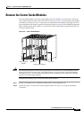
Remove the Single-Height Front Cards
Complete the following steps to remove single-height front cards from the chassis:
Step 1 Open the front door on the switch, as necessary.
Step 2 Connect a grounding strap to the ESD grounding jack or to the equipment rack.
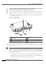
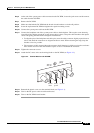
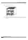
Step 3 Insert and press the flat-head tip of the 3-in-1 tool into the slot of the extractor lever at the top of the
front card until the latch springs open.
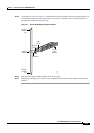
Figure 4-3 shows the location of the lever slot in relation to the
top of the front card.
Step 4 Pull the extractor lever to disconnect the front card from the midplane.