


3-43
Cisco MGX 8950 Hardware Installation Guide
Release 3, Part Number 78-14147-02 Rev. A0, November 2002
Chapter 3 Installing a Cisco MGX 8950
Installation Procedures
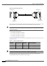
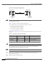
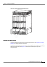
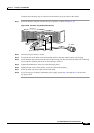
Figure 3-24 Power Interconnect Connections for DC
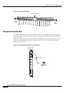
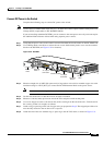
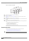
Connect the Back Cards
Connect the interfaces from the back cards to the appropriate end device. See Appendix B, “Cabling
Summary” for cabling specifications and pinouts.
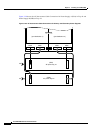
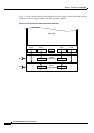
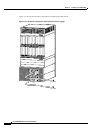
Once you have connected your back cards, route the cables through the cable management assembly. The
upper card set cables run to the upper cable management panel, and the lower card set cables run to the
bottom cable management panel.
Figure 3-25 shows cables routed through the upper cable
management panel.
44396
DC power
interconnect
cables