


2-21
Cisco MGX 8950 Hardware Installation Guide
Release 3, Part Number 78-14147-02 Rev. A0, November 2002
Chapter 2 Preparing for Installation
Required Tools and Equipment
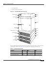
If you mount the Cisco MGX 8950 switch in a rack, ensure that the vertical hole spacing on the rack rails
meets industry standard (EIA/Retma) mounting hole pattern requirements. The Cisco MGX 8950 switch
and components fit in either a 19-inch wide rack or a 23-inch wide rack (with extenders installed). When
you install the Cisco MGX 8950 switch in a rack, allow enough room to access the back of the unit for
cabling and wiring purposes.
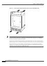
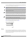
When a Cisco MGX 8950 switch is installed in a rack, it must be mid-mounted between the rack rails.
If a Cisco MGX 8950 switch is installed in an enclosure, it must be front mounted and supported by rear
support brackets.
Caution Make sure that mounting the equipment does not create a hazardous condition due to uneven
mechanical loading. The equipment rack should be securely supported.
Required Tools and Equipment
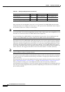
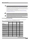
Table 2-6 lists the tools and equipment that you need to install and remove the Cisco MGX 8950
switch components.
Note For additional cabling requirements, see Appendix B, “Cabling Summary.”
Ta b l e 2-6 Tool and Equipment Requirements Checklist
Check Tools and Equipment
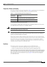
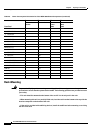
Hardware Components and Cables
Cisco MGX 8950 switch, with the front cards and back cards already installed
If your configuration was not installed in a Cisco-supplied rack, you will need the following
components for your system:
• Cabinet or rack that meets the RETMA Standard EIA-310-D requirements
• Upper and lower fan trays
• Air intake plenum
• Exhaust plenum
• AC power supply tray with power supplies—For AC-powered systems
• DC PEM—For DC-powered systems
Blank faceplates, as necessary;
• Single-height service module: Cisco Part Number SINGLE SM-CVR
• Double-height service module: Cisco Part Number DOUBLE SM-CVR
• PXM45/B: Cisco Part Number PROCESSOR CVR
Mounting kit option for 23-inch rack: Cisco Part Number MGX-MNT23-8950
Cable management assembly: Cisco Part Number: MGX8950-CAB-MGMT
Switch earthing conductor—Minimum of 6 AWG stranded copper wire, rated at minimum
90°C
APS connector, as necessary—Cisco Part Number MGX-APS-CON