


1-18
Cisco MGX 8950 Hardware Installation Guide
Release 3, Part Number 78-14147-02 Rev. A0, November 2002
Chapter 1 Product Overview
System Hardware Components
Faceplate Features
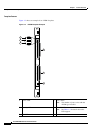
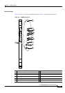
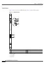
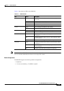
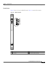
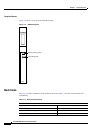
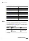
Figure 1-7 shows a close-up of an RPM-PR faceplate. Table 1-9 contains LED descriptions.
Figure 1-7 RPM-PR Faceplate
1 CPU OK LED 4 LM
1
1 OK and LM2 OK LEDs
1. LM = line module
2 CB
2
TX
3
LED
2. CB = cell bus
3. TX = transmit
5 Auxiliary port
3 CB RX
4
LED
4. RX = receive
6 Console port
84492
LM2 OK
AUX
RPM-PR
LM1 OK
CB RX
CB TX
CPU OK
CONSOLE
LM2 OK
LM1 OK
CB RX
CB TX
CPU OK
1
2
3
5
6
4