


2-19
Cisco MGX 8950 Hardware Installation Guide
Release 3, Part Number 78-14147-02 Rev. A0, November 2002
Chapter 2 Preparing for Installation
Site Requirements
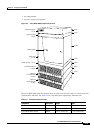
Note For more information about the DC PEM, see the “DC PEM” section on page 1-50.
DC power sources must be dedicated DC branch circuits. Each branch circuit must be protected by a
dedicated circuit breaker. The circuit breaker must have a rated trip delay time greater than that of the
Cisco MGX 8950 circuit breaker. The Cisco MGX 8950 switch uses a 100 A, 1-pole circuit breaker with
a short trip delay on each –48 V input. We recommend that the site have a dedicated 100 A, 1-pole circuit
breaker with a medium trip delay at each branch circuit.
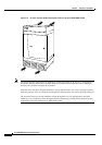
Connect the safety grounding wire to a solid earth ground. We recommend a ring terminal lug to
terminate the ground conductor at the ground stud. For details, see the
“Bonding and Grounding the
Cisco MGX 8950” section on page C-8.
Caution The –48 VDC return, logical grounds, and safety grounds are connected to the equipment chassis;
therefore, you must use a low-impedance connector to connect the chassis ground to the earthing ground.
Note Connect the Cisco MGX 8950 switch only to a –48 VDC source that complies with the SELV
requirements in UL 1950, IEC 950, EN 60950, and CSA C22.2 No. 950-95.
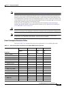
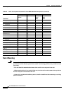
Power Consumption Calculation Tables
You can use Table 2-5 to calculate the typical power requirement for a Cisco MGX 8950 switch.
Ta b l e 2-5 Power Consumption Calculation for Cisco MGX 8950 Switch Components
Front Card
A B C D
Number of Cards
Installed
Watts Per Card Total Card
Power
(AxB)
Total 48V Current
(ADC)
(C/48)
AXSM-1-2488/B 85.8
• SMFLR-1-2488/B 19.4
• SMFSR-1-2488/B 19.4
• SMFXLR-1-2488/B 19.4
AXSM-4-622/B 94.6
• SMFIR-2-622/B 12
• SMFLR-2-622/B 12
AXSM-16-155/B 94.6
• MMF-8-155-MT/B 21.3
• SMB-4-155 25
• SMFIR-8-155-LC/B 12
• SMFLR-8-155-LC/B 12
AXSM-16-T3E3/B 94.6
• SMB-8-E3 10
• SMB-8-T3 10