


3-22
Cisco MGX 8950 Hardware Installation Guide
Release 3, Part Number 78-14147-02 Rev. A0, November 2002
Chapter 3 Installing a Cisco MGX 8950
Installation Procedures
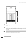
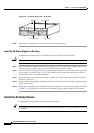
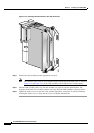
Remove the Back Cards
Complete the following steps to remove back cards from the switch:
Caution Do not use a power screwdriver on captive screws.
Step 1 Record the location of all the cards before you remove them.
Step 2 Use the flat-head or Phillips tip of the 3-in-1 tool to loosen the two captive screws located on the top and
bottom of the back card faceplate.
Step 3 Pull each of the two extractor levers, located at the top and bottom of the faceplate, out to the horizontal
position.
Step 4 Pull evenly on the two extractor levers to remove the back card from the card cage.
Step 5 Place the back card in an antistatic bag or on an antistatic bench.
Step 6 Repeat Step 2 through Step 5 for each back card that you are removing from the switch.
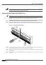
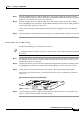
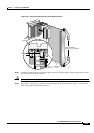
Remove the Back Cards from an APS Assembly
Complete the following steps to remove back cards from an APS assembly and to remove the APS
connector from the switch:
Caution An APS assembly consists of two optical AXSM back cards, an active card and a standby card, which
are connected using an APS connector (Cisco Part Number MGX-8950-APS-CON).
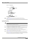
Caution A rocking motion during connector mating can bend or damage the APS connector pins.
Step 1 Remove one of the back cards connected to the APS assembly
a. Use the flat-head or Phillips tip of the 3-in-1 tool to loosen the two captive screws located on the top
and bottom of the back card faceplate.
b. Pull each of the two extractor levers, located at the top and bottom of the faceplate, out to the
horizontal position.
c. Pull evenly on the two extractor levers to remove the back card from the APS connector.
d. Repeat Step 1a through Step 1c for the remaining back card in the APS connector. The APS
connector will still be connected to the second back card when it is removed and will come out of
the switch with the card.
Step 2 Carefully separate the second back card from the APS connector by pulling it out with a straight motion.
Step 3 Place the back cards and APS connector in antistatic bags or on an antistatic bench.
Step 4 Repeat Step 1 through Step 3 for any remaining APS assemblies.