


3-5
Cisco MGX 8950 Hardware Installation Guide
Release 3, Part Number 78-14147-02 Rev. A0, November 2002
Chapter 3 Installing a Cisco MGX 8950
Installation Procedures
Installation Procedures
Caution Verify that the switch is not receiving power while you are installing the components.
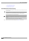
The following sections provide installation procedures for the Cisco MGX 8950 system:
• Install Stability Plate for Seismic Anchoring, page 3-6
• Ground the Frame Bonding Ground Connection for a Cisco-Supplied Rack, page 3-9
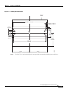
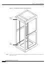
• Measure Rack Space, page 3-11
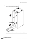
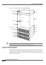
• Prepare for Rack Installation, page 3-12
• Install the AC Power Supply Tray(s), page 3-15
• Install the Air Intake Plenum, page 3-18
• Install the Lower Fan Tray, page 3-19
• Install the Cisco MGX 8950 Switch—Without a Mechanical Lift, page 3-20
• Install the Cisco MGX 8950 Switch—with a Mechanical Lift, page 3-29
• Install the Upper Fan Tray, page 3-31
• Install the Exhaust Plenum, page 3-31
• Install the DC PEM(s), page 3-32
• Install the Cable Management Assembly, page 3-33
• Connect the Fan Tray Power Cables to the Cisco MGX 8950 Switch, page 3-33
• Connect the AC Power Supply Tray to the Cisco MGX 8950 Switch, page 3-35
• Connect the DC PEM to the Cisco MGX 8950 Switch, page 3-39
• Connect the Back Cards, page 3-43
• Connect the Console Port, page 3-44
• Connect Power to the Cisco MGX 8950 Switch, page 3-45
• Connect the External Clock, page 3-50
• Connect the Alarms, page 3-53
Step 20
• Connect the Alarms, page
3-53 (optional)
• Connect the Alarms, page
3-53 (optional)
Step 21
• Connect the MP Connection,
page 3-53 (optional)
• Connect the MP Connection,
page 3-53 (optional)
Step 22
• Connect the LAN1/2 Ports,
page 3-54 (optional)
• Connect the LAN1/2 Ports,
page 3-54 (optional)
Step 23
• Verify EMI Compliance, page
3-55
• Verify EMI Compliance, page
3-55
Table 3-1 Installation Checklist—Cisco MGX 8950 System (continued)
Check Steps
Rack Mounted System (without
Lift) Rack Mounted System (with Lift) Cisco Cabinet System