


4-3
Cisco MGX 8950 Hardware Installation Guide
Release 3, Part Number 78-14147-02 Rev. A0, November 2002
Chapter 4 Maintaining the Cisco MGX 8950 Switch
Swap a Primary or Redundant DC PEM with Power On
Step 6 At the end of the system power cable connected to the DC PEM, loosen the jack screws and disconnect
the cable from the DC PEM.
Step 7 Remove the DC PEM.
Step 8 Make sure that both the DC PEM and the branch circuit breakers are in the off position.
Step 9 Insert the replacement DC PEM and tighten the captive mounting screws.
Step 10 Connect the system power cable at the DC PEM.
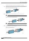
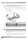
Step 11 Connect the backplane end of the system power cable to the backplane. This requires some dexterity,
especially if the cabling around the system power cable is dense. Grasp the cable bracket at the captive
screws and gently push the bracket straight in. Furthermore:
• To align the pins of the backplane and cable pins, move the cable connector slightly up and down or
side to side until the connectors are aligned and able to mate. When executing this step, keep the
bracket as level as possible.
• The connector is fully inserted when the connector shell (housing) is all the way into the enclosure
hole and the exterior of the shell with the captive screws is flush with the enclosure.
Step 12 Tighten the connector screws.
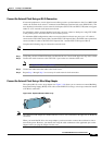
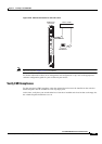
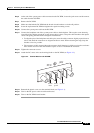
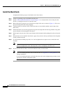
Step 13 Attach the DC source wires at the wiring block on the DC PEM (see Figure 4-2).
Figure 4-2 Terminal Block on the DC PEM
Step 14 Reattach the plastic cover over the terminal block (see Figure 4-1).
Step 15 Turn on the DC power at the circuit branch source.
Step 16 Turn on the DC PEM circuit breaker.
48 VDC
return
Safety
g
round
–48 VDC
38228
-48V
RTN