


1-34
Cisco MGX 8950 Hardware Installation Guide
Release 3, Part Number 78-14147-02 Rev. A0, November 2002
Chapter 1 Product Overview
System Hardware Components
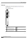
RJ45-FE
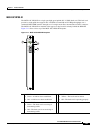
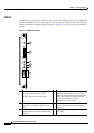
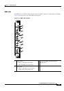
The RJ45-FE back card has an RJ-45 connector to attach to Category 5 UTP for 100BaseTX, and a media
independent interface (MII) connector that permits connection through external transceivers to
multimode fiber for 100BaseFX physical media.
Figure 1-18 shows a close-up of the RJ45-FE faceplate.
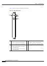
Figure 1-18 RJ45-FE Faceplate
1 Enabled LED
• Green—The back card is active.
• Off—The back card is not active.
4 LINK LED—When the RJ45 port is active,
this LED is on when the back card is receiving
a carrier signal from the network. When the
MII port is active, this LED indicates network
activity, and it flickers on and off
proportionally to this activity.
2 MII connector—Can be used with a variety of
transceivers to connect to different media
types.
5 RJ45 LED—When lit, this LED indicates that
the RJ45 connector has been enabled by the
software.
3 MII LED—When lit, this LED indicates that
the MII connector has been enabled by the
software.
6 RJ45 connector—Used for connection to
100BaseT media.
84498
ENABLED
MII
RJ45
LINK
P
O
R
T
1
RJ45-FE
1
2
3
4
5
6