


3-53
Cisco MGX 8950 Hardware Installation Guide
Release 3, Part Number 78-14147-02 Rev. A0, November 2002
Chapter 3 Installing a Cisco MGX 8950
Installation Procedures
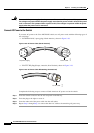
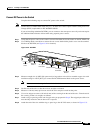
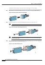
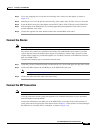
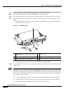
Step 4 Use a wire-wrapping tool to wrap the two remaining wires to the pin of the adapter, as shown in
Figure 3-37.
Step 5 Slide the pin cover over the pins and onto the body of the adapter after all of the wires are connected.
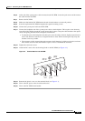
Step 6 Insert the RJ-45 connector of the adapter into the EXT CLK1 or EXT CLK2 port on the PXM-UI-S3.
Step 7 If the faceplate of the PXM-UI-S3 has a mating tapped hole, hand tighten the strain-relief screw to
provide additional strain relief.
Step 8 Connect the opposite end of the shielded cable to the external BITS clock source.
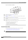
Connect the Alarms
Note This step is optional.
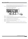
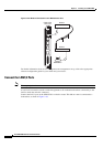
Dry contact relay closures are available for forwarding Cisco MGX 8950 switch alarms to an alarm
system. Separate visual and audible alarm outputs are available for critical, major, and minor alarm
outputs and the outputs are provided through the use of a DB15 connector on the PXM user interface
back card (PXM-UI-S3).
Complete the following steps to connect the external clock:
Step 1 Verify that you have a PXM-UI-S3 back card installed in slots 7 and 8 in the upper rear bay of the switch.
Step 2 Connect the DB15 cable to the ALARM port on the PXM-UI-S3 back card.
Note See Appendix B, “Cabling Summary” for cable requirements.
Step 3 Connect the other end of the cable to the alarm source.
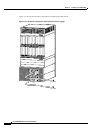
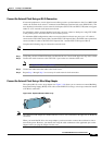
Connect the MP Connection
Note This step is optional.
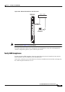
A dial-up connection extends switch management to all workstations that have access to the Public
Switch Telephone Network (PSTN).
Connect the maintenance port (MP) port on the PXM-UI-S3 to a modem. Connect the terminal to a
power source and set it up using the values that are shown in
Table 3-4. This modem is connected through
the PSTN and is accessible from a workstation, as shown in Figure 3-38.