


3-51
Cisco MGX 8950 Hardware Installation Guide
Release 3, Part Number 78-14147-02 Rev. A0, November 2002
Chapter 3 Installing a Cisco MGX 8950
Installation Procedures
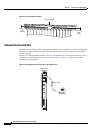
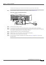
Connect the External Clock Using an RJ-45 Connection
If external equipment or a local digital central office provides synchronization to the Cisco MGX 8950
switch, the external clock source is connected to the PXM user interface back card (PXM-UI-S3). The
user interface back card has as two external clock inputs (EXT CLK1 and EXT CLK2) that can support
either T1 or E1 external clock input, but not both.
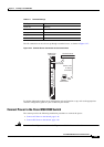
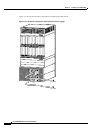
For redundancy where one user interface back card is present, connect to both ports, using EXT CLK1
as the primary source and EXT CLK2 as the secondary source.
For redundant PXM configurations where two user interface back cards are preset, use a Y-cable to
connect to the EXT CLK1 input of Slot 7 and the EXT CLK1 input of Slot 8. For BITS source protection,
connect another Y-cable to the EXT CLK2 input of Slot 7 and the EXT CLK2 input of Slot 8.
Complete the following steps to connect the external clock:
Tip Cisco recommends that you label each data cable at both ends to identify its destination.
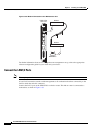
Step 1 Verify that you have a PXM-UI-S3 back card installed in slots 7 and 8 in the upper rear bay of the switch.
Step 2 Connect the cable connector to the EXT CLK 1 port on the user interface back card.
Note See Appendix B, “Cabling Summary” for cable requirements.
Step 3 Connect the other end of the cable to the clock source.
Step 4 Repeat Step 1 through Step 3 as necessary for each external clock connection.
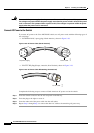
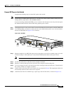
Connect the External Clock Using a Wire-Wrap Adapter
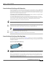
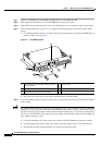
The optional RJ-45 to wire-wrap adapter (see Figure 3-34) allows you to connect an external Building
Integrated Timing Supply (BITS) clock source to the PXM-UI-S3 using a wire-wrap connection instead
of an RJ-45 connection.
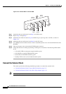
Figure 3-34 Optional RJ-45 to Wire-wrap
Note The eight pins of the adapter are marked and have a one-to-one correlation to the eight lines on the RJ-45
connector.
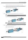
When you install the RJ-45 to wire-wrap adapter, you do not need to remove the card from its slot or
turn off the power. However, you should wire-wrap the cable conductors to the applicable pins on the
adapter before you plug the adapter into the card.
52804