


1-48
Cisco MGX 8950 Hardware Installation Guide
Release 3, Part Number 78-14147-02 Rev. A0, November 2002
Chapter 1 Product Overview
System Hardware Components
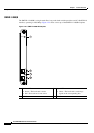
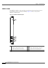
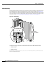
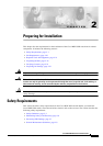
APS Assembly
For both equipment and fiber protection, the 1:1 APS line and card set redundancy configuration requires
that an APS connector to link two optical back cards: an active card and a standby card.
Figure 1-32
shows an example of two back cards installed in an APS connector. When the two back cards are linked
to an APS connector, they form an APS assembly. The APS assembly is installed in the switch. For more
information, see the
“1+1 Card and APS Line Redundancy—Intercard” section on page 1-5
Figure 1-32 APS Assembly
The following modules support the Cisco MGX 8950 APS connector (MGX-APS-CON-8950).
• AXSM-1-2488/B
• AXSM-4-622/B
• AXSM-16-155/B
For information on APS configuration, refer to the Cisco MGX 8850 (PXM45) and MGX 8950 Switch
Software Configuration Guide.
Top view
APS
connector
Back card
Alignment
slot
Card extractors
shown in "in" position
44143
Guide tabsGuide tabs