


3-20
Cisco MGX 8950 Hardware Installation Guide
Release 3, Part Number 78-14147-02 Rev. A0, November 2002
Chapter 3 Installing a Cisco MGX 8950
Installation Procedures
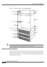
Install the Cisco MGX 8950 Switch—Without a Mechanical Lift
Because of the risk of damage to the cards, modules, and backplane, Cisco strongly recommends the use
of a mechanical lift. Using a lift greatly simplifies the installation and reduces the risk of damage. See
“Install the Cisco MGX 8950 Switch—with a Mechanical Lift” section on page 3-29 for more
information about installing the Cisco MGX 8950 switch with a mechanical lift.
Note If you are installing the Cisco MGX 8950 switch with a mechanical lift, proceed to the “Install the Cisco
MGX 8950 Switch—with a Mechanical Lift” section on page 3-29.
If a mechanical lift is not available for installation, the switch must be manually lifted into place. Since
the switch is shipped with all components pre-installed, you will have to remove the cards and modules
from the switch to easily lift it into the rack.
The following sections contain instructions for installing a switch without the use of a mechanical lift:
• Prepare for Installation, page 3-20
• Remove the Front Cards, page 3-20
• Remove the Back Cards, page 3-22
• Remove the Back Cards from an APS Assembly, page 3-22
• Install the Switch in the Rack, page 3-23
• Reinstall the APS Assembly, page 3-24
• Reinstall the Back Cards, page 3-27
• Reinstall the Front Cards, page 3-28
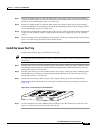
Tip If a component requires more than two screws to install it in the rack or cabinet, install the two bottom
screws first.
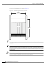
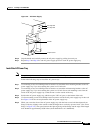
Prepare for Installation
Review the following guidelines before installation begins:
• Before removing any cards, modules, or assemblies, we recommend that you carefully note and
write down their location or slot number in the switch.
• Verify that your ESD grounding wrist strap is properly connected. See the “Preventing ESD
Damage” section on page 2-7 for detailed information about ESD procedures.
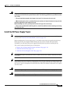
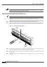
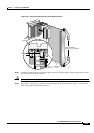
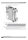
Remove the Front Cards
Complete the following steps to remove front cards from the switch:
Note The card should slide in and out with only slight friction on the adjacent board’s EMI gaskets. Do not
force the card. Investigate any binding.
Single-height front cards have an extractor lever at the top of the faceplate to secure them into the card
cage. Double-height front cards have an extractor lever at both the top and the bottom of the faceplate.