


3-4
Cisco MGX 8950 Hardware Installation Guide
Release 3, Part Number 78-14147-02 Rev. A0, November 2002
Chapter 3 Installing a Cisco MGX 8950
Installation Checklist
Step 9
• Install the Upper Fan Tray,
page 3-31
• Install the Upper Fan Tray,
page 3-31
• Connect the External Clock,
page 3-50 (optional)
–
Connect the External
Clock Using an RJ-45
Connection, page 3-51
–
Connect the External
Clock Using a Wire-Wrap
Adapter, page 3-51
Step 10
• Install the Exhaust Plenum,
page 3-31
• Install the Exhaust Plenum,
page 3-31
• Connect the Alarms, page
3-53 (optional)
Step 11
• Install the DC PEM(s), page
3-32, as necessary
• Install the DC PEM(s), page
3-32, as necessary
• Connect the MP Connection,
page 3-53 (optional)
Step 12
• Install the Cable Management
Assembly, page 3-33
• Install the Cable Management
Assembly, page 3-33
• Connect the LAN1/2 Ports,
page 3-54 (optional)
Step 13
• Connect the Fan Tray Power
Cables to the Cisco MGX
8950 Switch, page 3-33
• Connect the Fan Tray Power
Cables to the Cisco MGX
8950 Switch, page 3-33
• Verify EMI Compliance, page
3-55
Step 14
• Connect the AC Power Supply
Tray to the Cisco MGX 8950
Switch, page 3-35,
as necessary
• Connect the AC Power Supply
Tray to the Cisco MGX 8950
Switch, page 3-35,
as necessary
Step 15
• Connect the DC PEM to the
Cisco MGX 8950 Switch,
page 3-39, as necessary
• Connect the DC PEM to the
Cisco MGX 8950 Switch,
page 3-39, as necessary
Step 16
• Connect the Back Cards, page
3-43
• Connect the Back Cards, page
3-43
Step 17
• Connect the Console Port,
page 3-44
• Connect the Console Port,
page 3-44
Step 18
• Connect Power to the Cisco
MGX 8950 Switch, page 3-45
–
Connect AC Power to the
Switch, page 3-46
–
Connect DC Power to the
Switch, page 3-49
• Connect Power to the Cisco
MGX 8950 Switch, page 3-45
–
Connect AC Power to the
Switch, page 3-46
–
Connect DC Power to the
Switch, page 3-49
Step 19
• Connect the External Clock,
page 3-50 (optional)
–
Connect the External
Clock Using an RJ-45
Connection, page 3-51
–
Connect the External
Clock Using a Wire-Wrap
Adapter, page 3-51
• Connect the External Clock,
page 3-50 (optional)
–
Connect the External
Clock Using an RJ-45
Connection, page 3-51
–
Connect the External
Clock Using a Wire-Wrap
Adapter, page 3-51
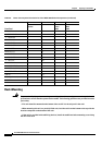
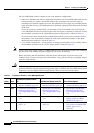
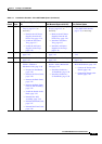
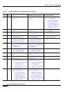
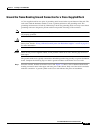
Table 3-1 Installation Checklist—Cisco MGX 8950 System (continued)
Check Steps
Rack Mounted System (without
Lift) Rack Mounted System (with Lift) Cisco Cabinet System