


5-57
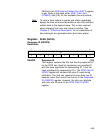
FE Fetch Enable 6
The internal opcode fetch signal is presented on GPIO0
if this bit is set, regardless of the state of bit 0
(GPIO0_EN).
R Reserved 5
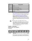
GPIO_EN[1:0] GPIO Enable [1:0]
These bits power up set, causing the GPIO1 and GPIO0
pins to become inputs. Resetting these bits causes
GPIO[1:0] to become outputs.
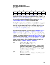
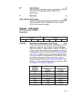
Register: 0x48 (0xC8)
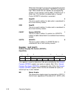
SCSI Timer Zero (STIME0)
Read/Write
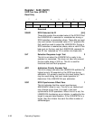
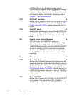
HTH[3:0] Handshake-to-Handshake Timer Period [7:4]
These bits select the handshake-to-handshake time-out
period, the maximum time between SCSI handshakes
(SREQ/ to SREQ/ in target mode, or SACK/ to SACK/ in
initiator mode). When this timing is exceeded, an interrupt
is generated and the HTH bit in the SCSI Interrupt Status
One (SIST1) register is set. The following table contains
time-out periods for the Handshake-to-Handshake Timer,
the Selection/Reselection Timer (bits [3:0]), and the
General Purpose Timer (SCSI Timer One (STIME1) bits
[3:0]). For a more detailed explanation of interrupts, refer
to Chapter 2, “Functional Description.”
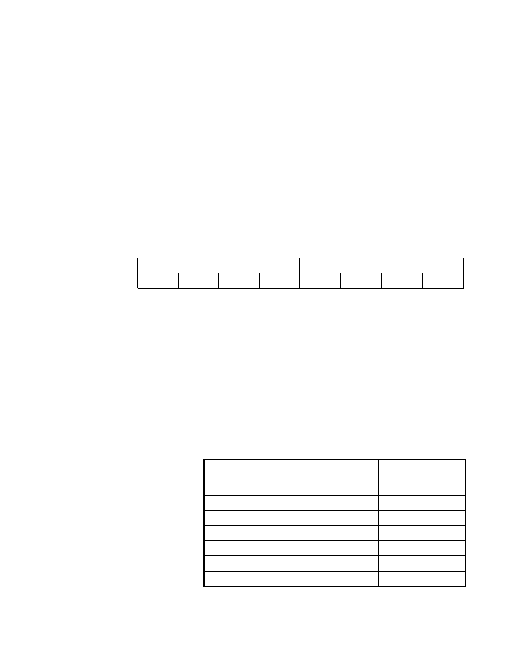
7430
HTH[3:0] SEL[3:0]
00000000
HTH[7:4],
SEL[3:0],
GEN[3:0]
1
Minimum Timeout
(40 MHz)
Minimum Timeout
(50 MHz)
0000 Disabled Disabled
0001 125 µs 100 µs
0010 250 µs 200 µs
0011 500 µs 400 µs
0100 1 ms 800 µs
0101 2 ms 1.6 ms