


AC Characteristics 7-11
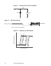
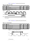
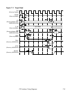
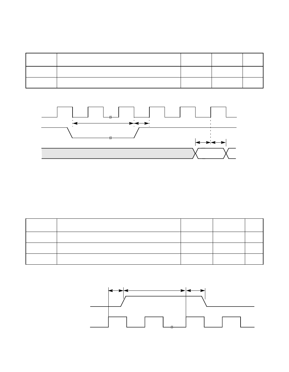
Table 7.14 and Figure 7.7 provide reset input timing data.
Figure 7.7 Reset Input
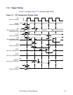
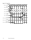
Table 7.15 and Figure 7.8 provide interrupt output timing data.
Figure 7.8 Interrupt Output Waveforms
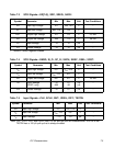
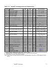
Table 7.14 Reset Input Timing
Symbol Parameter Min Max Unit
t
1
Reset pulse width 10 – t
CLK
t
2
Reset deasserted setup to CLK HIGH 0 – ns
t
2
1. When enabled.
CLK
RST/
MAD
1
Valid Data
t
3
t
4
t
1
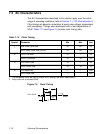
Table 7.15 Interrupt Output
Symbol Parameter Min Max Unit
t
1
CLK HIGH to IRQ/ LOW – 20 ns
t
2
CLK HIGH to IRQ/ HIGH – 40 ns
t
3
IRQ/ deassertion time 3 – CLK
CLK
IRQ/
t
3
t
1
t
2