


Installing and Cabling the Cabinets
112 Installation, Upgrades and Additions for Avaya CMC1 Media Gateways
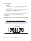
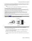
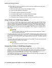
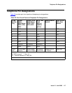
Figure 45: Connectors on the P333T-PWR switch
2. Insert the other end of the power cord into a nonswitched electrical outlet or the connector
on the BUPS.
The unit powers up and performs a self-test procedure. The LEDs flash at regular intervals
after the self-test procedure is completed successfully.
Power up—DC input (optional)
The P333T-PWR switch can operate on the AC input only. However, you may wish to use the
optional DC input for the following:
● Backup for the power over Ethernet ports
● To provide more than 200 watts for the power over Ethernet ports
Note:
Note: Please refer to the P333T-PWR switch User’s Guide for more information.
Connect the Cables
Connect IP telephones, PCs, servers, routers, workstations, and hubs as follows:
1. Connect the Ethernet connection cable (not supplied) to a 10/100 megabits per second port
on the front panel of the Avaya P333T-PWR switch.
Note:
Note: Use standard RJ45 connections and a CAT5 cable for 100 megabits per second
operation.
2. Connect the other end of the cable to the Ethernet port of the PC, server, router,
workstation, IP telephone, switch, or hub.
Note:
Note: Use a crossover cable when connecting the Avaya P333T-PWR switch to a
switch or hub.
3. Check that the appropriate link (LNK) LEDs light up.
Figure notes:
1. BUPS connector 2. AC connector
scdlp333 KLC 082002
INPUT
Amax
Vin
44-57V 15A
BUPS
INPUT
1
2