Install and Wire Telephones and Trunks
Issue 10 June 2005 87
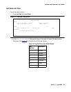
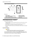
Refer to Figure 21: Example MDF Connections on page 63 for punch-down information for
common circuit packs. The figure shows the colors of the punch-downs and is best viewed from
CD-ROM or on-line.
After installing the hardware, the data for the system and telephone features is administered.
These procedures are provided in Administrator’s Guide for Avaya Communication Manager.
DCP, analog, and ISDN-BRI
The 302D Attendant Console describes a typical telephone connection. This information is
typical of the 603E, 84xx (4-wire), and 94xx telephones. The attendant console always requires
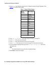
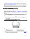
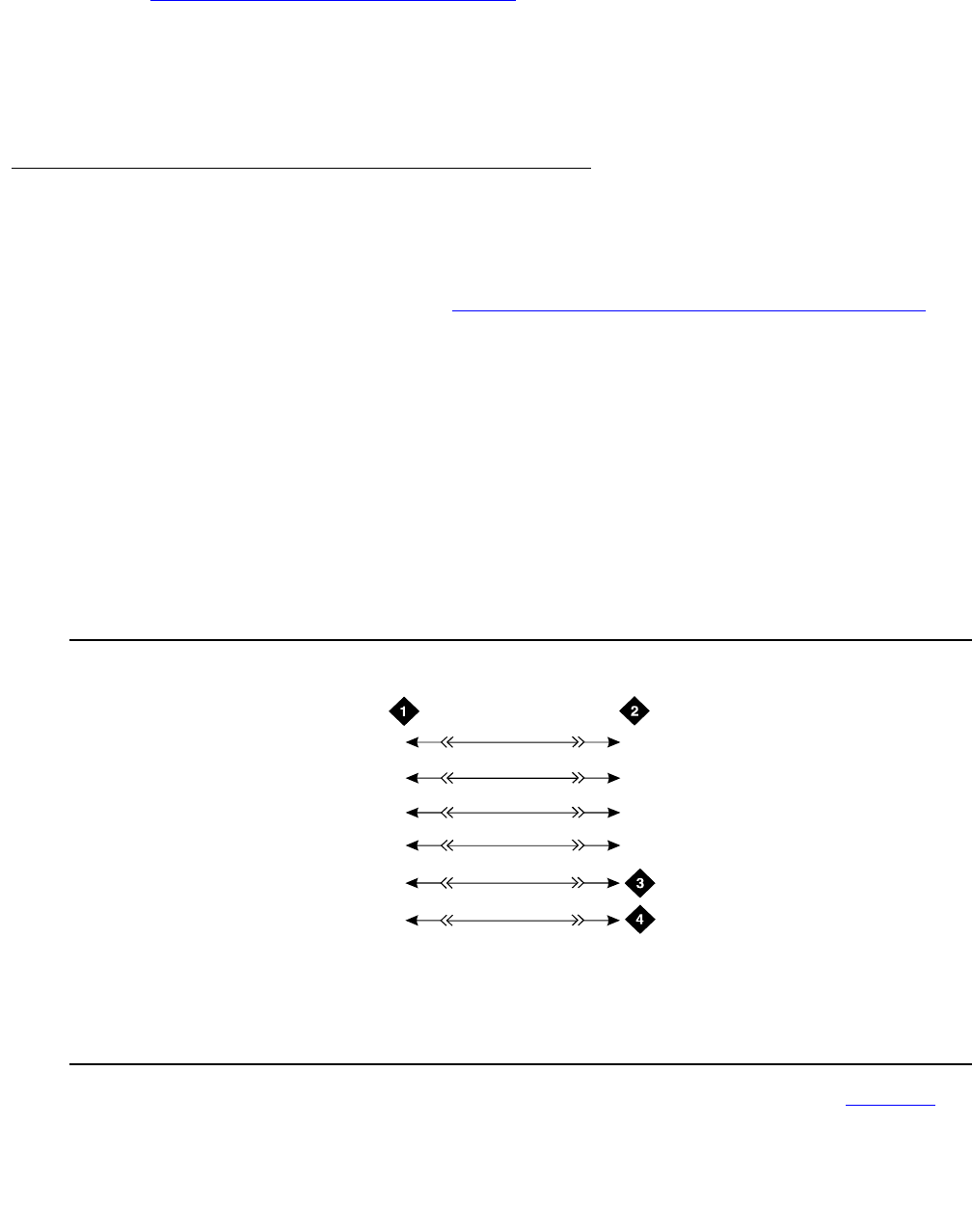
auxiliary (adjunct) power (-48 VDC). See Figure 32: 302D to Digital Line Circuit Pack Wiring
on
page 87. Only 1 console can be powered by the system through the AUX connector. The
primary console should be powered from the system so it has the same power failure backup as
the system.
The maximum cabling distance for the console powered from the cabinet is 350 feet (100 m)
using 24 AWG (#5) (0.26 mm
2
) wire.
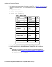
The general steps to connect a telephone are:
1. Choose a device to connect such as a 302D Attendant Console.
2. Choose the port circuit pack and its carrier and slot number, such as TN754C, Cabinet 1,
Carrier A, Slot 06.
3. Choose a port circuit on the port circuit pack, such as Port 05.
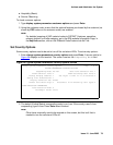
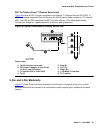
Figure 32: 302D to Digital Line Circuit Pack Wiring
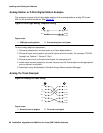
4. Install cross-connect jumpers to wire the terminal to the port circuit pack. See Figure 32.
This pinout is for a 4-wire Digital Line circuit pack.
Figure notes:
1. 302D attendant console
2. 4-wire digital line circuit pack
3. -48 VDC from adjunct power
4. Ground from adjunct power
30
2
c
wir
e
RPY
0
12
098
1
39
14
40
15
2
3
6
7
8
TXT
TXR
PXT
PXR
TXT5
TXR
5
PXT5
PXR5


