


Adding or Removing Hardware
344 Installation, Upgrades and Additions for Avaya CMC1 Media Gateways
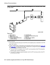
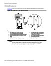
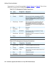
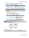
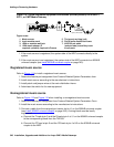
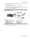
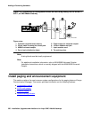
The pinouts for J1, J2, and J3 are provided in Table 63, Table 64, and Table 65. Refer to these
tables when connecting music or paging equipment.
Table 63: J1 Pin Assignments (System Connections)
Pin Color Designation Description
1 White-Orang
e
— Not Used
2 Orange PG2/BZ2 Seizure control lead, connected to -48 VDC
from the system or from the 909A/B when the
protection paging switch is set to C2, or to -48
VDC on the 909A/B when protection/paging
switch is set to C1
3 White-Green PG1/BZ1 Seizure control lead, connected to SZ lead
from the AUX trunk when the protection/
paging switch is set to C2, or to -48 VDC on
the 909A/B when the protection/paging switch
is set to C1
4 Blue R Ring lead
5 White-Blue T Tip lead
7 Green BSY2/BY2 Busy/busy-out lead, connected to S1 lead
from the AUX trunk
7 White-Brown BSY1/BY1 Busy/busy-out lead, connected to S lead from
the AUX trunk
8 Brown — Not Used
Table 64: J2 Pin Assignments (Accessory Connections)
Pin Color Designation Description
1 White-Orang
e
CMS1/M1 Customer-supplied music source
2 Orange CMS2/M2 Customer-supplied music source
3 White-Green COS1 Remote busy-out control contact closure from
music source
4 Blue CR Customer ring lead
5 White-Blue CT Customer tip lead
1 of 2