


Installing and Cabling the Cabinets
144 Installation, Upgrades and Additions for Avaya CMC1 Media Gateways
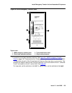
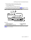
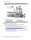
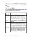
Figure 66: Connections for Telephone Used for Emergency Transfer and as Normal
Extension
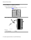
Install Telephone for Power Transfer Unit
Trunk/Auxiliary Field: Telephone Used Only for Emergency Transfer
To connect the telephone to the trunk/auxiliary field:
1. Connect a pair of wires between the -48V and GRD terminals on the yellow emergency
transfer row/connecting block and the EM TRANS RELAY PWR terminal. See
Figure 65: Connections for Telephone Used for Emergency Transfer
on page 143.
2. Connect CO trunk leads from the purple field to the TC terminals on the yellow emergency
transfer row/connecting block for each trunk.
3. Connect CO trunk leads from the green field to the TK terminals on the yellow emergency
transfer row/connecting block for each trunk.
Figure notes:
1. To network interface facility
2. To blue or white station field
3. To analog line circuit pack
4. To CO trunk circuit pack
5. To power transfer unit
6. To control carrier AUX connector
TC TK LC ST
1M 1m 2M 2m 3M
ALARM MONITORS EM TRANS RELAY PWR ACC PWR
3m 3w
TC TK LC ST TC TK LC ST TC TK LC ST TC TK LC ST
C
O
M
1
N
O
1
N
C
2
N
C
1
C
O
M
2
N
O
2
C
O
M
3
N
C
3
G
R
D
-48
V
2820
10
35
EMXR
ST
ST
7
5 76 83 4
r758582b MMR 042996