


Adding or Removing Hardware
352 Installation, Upgrades and Additions for Avaya CMC1 Media Gateways
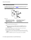
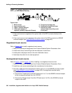
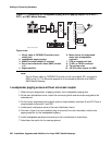
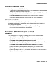
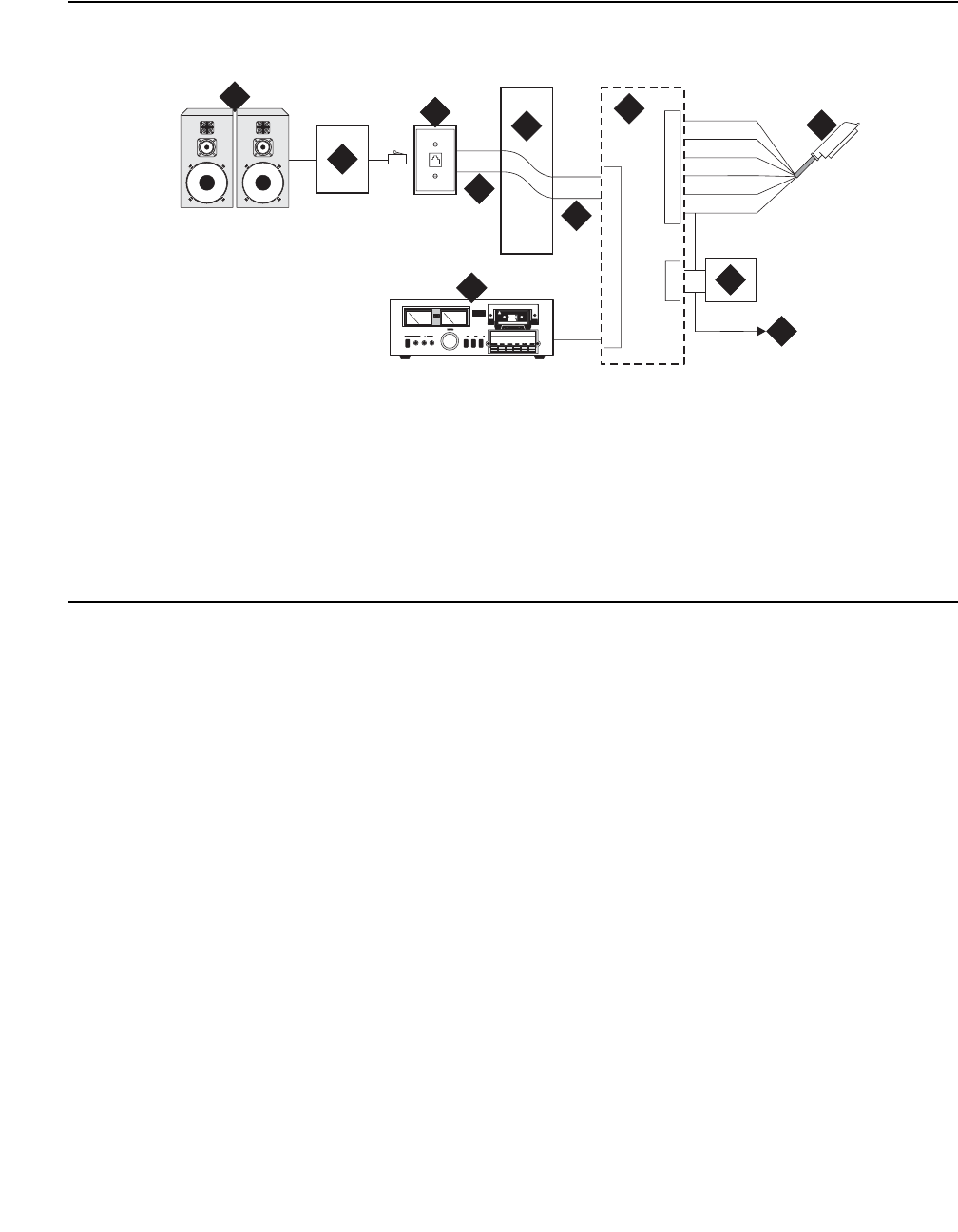
Figure 117: Connections for loudspeaker paging without paging adapter for an MCC1,
SCC1, or CMC1 Media Gateway
Note:
Note: On the 25-pair cable to TN763B/C/D auxiliary trunk circuit pack, SZ1 connects to
GRD on key 10. The 50 points amphenol is connected to the back of a G600 or
G650 Media Gateway.
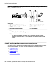
Loudspeaker paging access without universal coupler
1. Determine port assignment of paging zone(s) from loudspeaker paging form.
2. At the main distribution frame, locate the connecting block and terminals assigned to the
selected port.
3. On the locally engineered wiring block, place a strap between terminals S and SZ. Place a
strap between terminals S1 and SZ1.
4. Install patch cord/jumper wires at the main distribution frame.
5. Connect a 2-pair line cord (modular plug at one end) from the information outlet to the
paging amplifier (to the loudspeaker system).
6. Install loudspeaker equipment according to the manufacturer’s instructions.
7. Administer the switch for the new equipment.
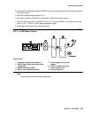
Figure notes:
1. 25-pair cable to TN763B/C/D auxiliary trunk
circuit pack
2. Loudspeaker paging system
3. 909A/B universal coupler (if required)
4. Part of main distribution frame (MDF) circuits
1-16
5. Paging amplifier
6. Music source for background
music over loudspeakers
(optional)
7. 103A or modular wall jack
8. To SZ1 on TN763 connector
9. Tip and ring wires
10. -48 VDC power supply for 909B
cydfnzm KLC 091202
J2
J3
J1
5
1
2
2
7
4
4
5
2
3
6
5
1
2
3
4
5
7
8
9
9
10
6