


Install Emergency Transfer Unit and Associated Telephones
Issue 10 June 2005 139
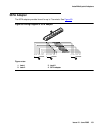
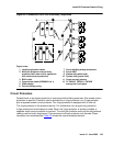
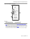
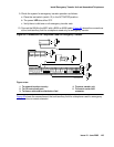
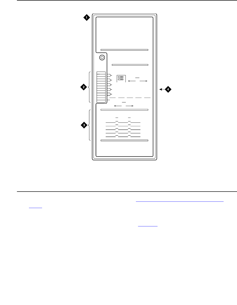
Figure 64: 808A Emergency Transfer Panel
3. Locate the circuit start selection switches. See Figure 64: 808A Emergency Transfer
Panel on page 139. These are the first 10 two-position switches on the left side of the 808A.
The switches set each of the 5 incoming trunk lines to either loop start or ground start. Two
switches are used for each of the 5 circuits; switches 1 and 2 are used for circuit 1, switches
3 and 4 are used for circuit 2, and so forth. See Table 25
.
For loop start, set the switches to the left. For ground start, set the switches to the right.
Figure notes:
1. 808A emergency transfer panel
2. Circuit start selection switches
3. Trunk identification label
4. 25-pair male connector
1
2
3
4
5
6
7
8
9
10
1
2
3
4
5
12
EMERGENCY
TRANSFER
PANE L
CIRCUIT
1
2
POWER
TRUNK/TEST SWITCHES
TRUNKOPTION
LOOP
START
GROUND
START
BOTH SWITCHES MUST BE
THROWN TO ACTIVATE
TRUNK OPTION
TRANSFER TEST SWITCH
ACTIVATED
NORMAL
OPERATION
TRUNK IDENTIFICATION
TRUNK
LINE
EXT LOC
808A
l
ed808a
L
J
K
0
4
0896