


Install Emergency Transfer Unit and Associated Telephones
Issue 10 June 2005 143
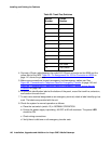
9. Check the system for emergency transfer operation as follows:
a. Place the test switch (switch 12) in the ACTIVATED position.
b. The power LED should be OFF.
c. Verify there is dial tone on all emergency transfer sets.
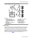
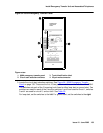
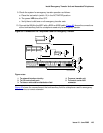
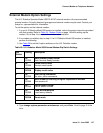
10. Connect the 808A to the MDF with a B25A or A25B cable. Figure 65
shows the connections
at the trunk/auxiliary field for a telephone used only for emergency transfer.
Figure 65: Connections for Telephone Used for Emergency Transfer
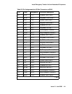
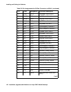
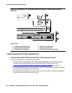
Figure 66 shows the connections at the trunk/auxiliary field for a telephone used for emergency
transfer and as a normal extension.
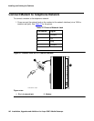
Figure notes:
1. To network interface circuitry
2. To CO trunk circuit pack
3. To blue or white station distribution field
4. To power transfer unit
5. To control carrier AUX
connector
TC TK LC ST
1M 1m 2M 2m 3M
ALARM MONITORS EM TRANS RELAYPWR ACC PWR
3m 3w
TC TK LC ST TC TK LC ST TC TK LC ST TC TK LC ST
C
O
M
1
N
O
1
N
C
2
N
C
1
C
O
M
2
N
O
2
C
O
M
3
N
C
3
G
R
D
-48
V
123
2822
25
50
1
EMXR
2822
r758580b MMR 042996