


Completing Installation and Cable Pinouts
162 Installation, Upgrades and Additions for Avaya CMC1 Media Gateways
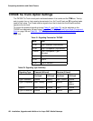
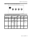
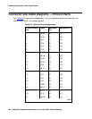
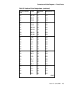
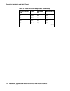
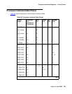
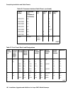
Connector and Cable Diagrams — Pinout Charts
See Table 35 for typical lead designations. The circuit packs and auxiliary equipment are
classified as shown in the following tables.
Table 35: Lead and Color Designations
Cross-Connect
Pin
Color Amphenol
Pin
Backplane Pin
1W-BL26102
2 BL-W 01 002
3 W-O 27 103
4 O-W 02 003
5 W-G 28 104
6 G-W 03 004
7W-BR29105
8 BR-W 04 005
9W-SL30106
10 SL-W 05 006
11 R-BL 31 107
12 BL-R 06 007
13 R-O 32 108
14 O-R 07 008
15 R-G 33 109
16 G-R 08 009
17 R-BR 34 110
18 BR-R 09 010
19 R-SL 35 111
20 SL-R 10 011
21 BK-BL 36 112
1 of 3