


Connector and Cable Diagrams — Pinout Charts
Issue 10 June 2005 169
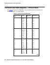
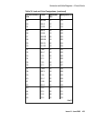
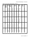
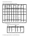
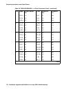
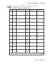
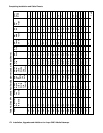
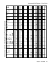
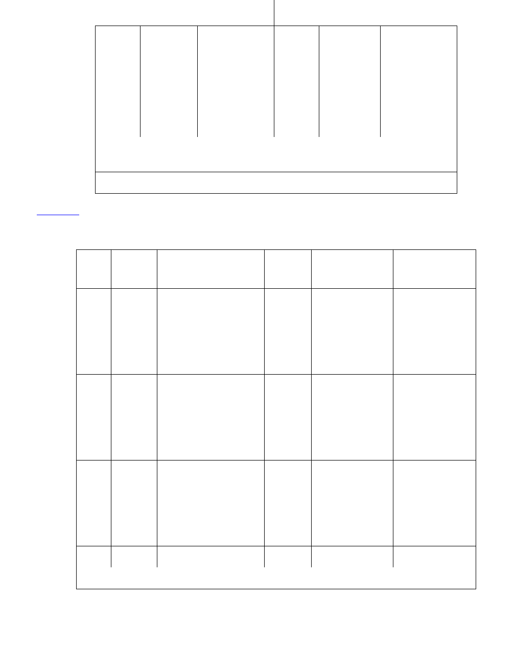
Table 39 shows the pinouts for theTN2185B ISDN-BRI 4-wire S Interface.
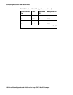
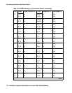
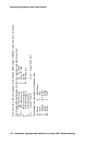
48 W-BR LO 09 W-BR LO
23 BR-W LO
(High) 01 \BR LO (High)
49 W-SL LOOP2 06 W-SL LOOP2
24 SL-W LOOP1 05 SL-W LOOP1
All other pins are empty.
Table 39: TN2185B ISDN-BRI — 4-Wire S Interface Pinout
Port Signal Cross-Connect
Pin
Color Amphenol
Pin
Backplane
Pin
1 TXT.1 1 W-BL 26 102
TXR.1 2 BL-W 01 002
PXT.1 3 W-O 27 103
PXR.1 4 O-W 02 003
2 TXT.2 5 W-G 28 104
TXR.2 6 G-W 03 004
PXT.2 7 W-BR 29 105
PXR.2 8 BR-W 04 005
3 TXT.3 9 W-SL 30 106
TXR.3 10 SL-W 05 006
PXT.3 11 R-BL 31 107
PXR.3 12 BL-R 06 007
4 TXT.4 13 R-O 32 108
1 of 2
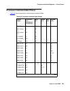
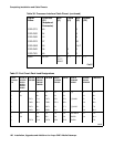
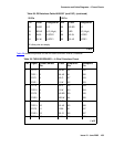
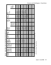
Table 38: DS1Interface Cable H600-307 (and C6C) (continued)
50-Pin 15-Pin
Pin Color Designation Pin Color Designation
2 of 2