


Connect External Alarms and Auxiliary Connections
Issue 10 June 2005 115
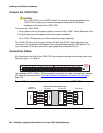
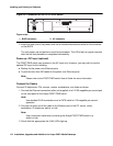
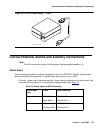
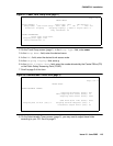
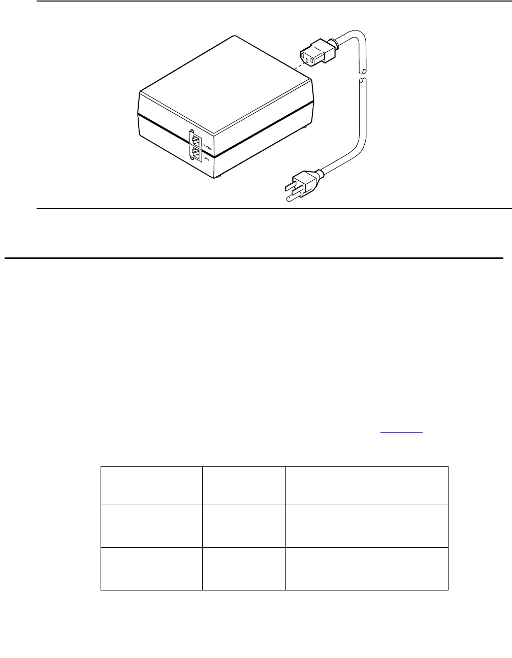
Figure 46: 1151B2 Power Supply — Front
Connect External Alarms and Auxiliary Connections
Note:
Note: The AUX connector is part of the Processor Interface cable assembly (J1).
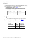
Alarm Input
Alarms can be generated on adjunct equipment, sent to the DEFINITY System, and recorded
and reported as “external alarms.” A typical major alarm input is from a UPS.
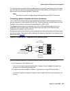
1. Connect 1 major alarm input wire pair and 1 minor alarm input wire pair to the auxiliary field
from the AUX connector (J1 on Processor Interface Cable). See Table 19
.
pwr_sup1 CJL 051496
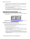
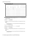
Table 19: Alarm Inputs at AUX Connector
Alarm Input
Type
Color AUX Connector
Major White-Blue AP1 (Pin 26)
Blue-White Ground (Pin 1)
Minor White-Orange AP2 (Pin 27)
Orange-White Ground (Pin 2)