


Install multimedia call handling (MMCH)
Issue 10 June 2005 321
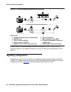
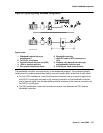
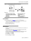
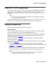
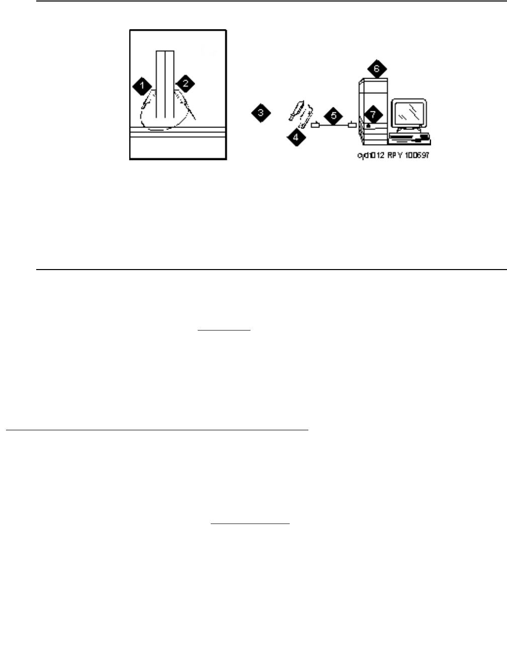
Figure 101: Typical multimedia call handling ESM connections
ESM installation
Use the following procedure and Figure 101 to connect to the ESM equipment:
1. Install the TN2207 primary rate interface (PRI) circuit pack and the TN787F/G/H/J/K
multimedia interface (MMI) circuit pack in the port carrier.
2. Record the circuit pack locations.
3. Connect the ESM Y-cable as shown.
Administration
1. Enter list configuration all, and a list of the installed carriers, circuit packs, and
ports appears.
2. Record the location (board number) of the new circuit packs and verify that all other
required circuit packs (refer to ESM installation
) are present.
3. Enter add DS1 xxxxx, (where xxxxx is the location of the TN2207 PRI circuit pack
recorded in step 2), and the DS1 circuit pack administration form appears.
4. Set the Name: field to ESM DS1
5. Set the Bit Rate: field to 2.048
6. Set the Line Coding: field to hdb3
Figure notes:
1. Port B Y-cable connector to a TN787
multimedia interface (MMI) circuit pack
2. Port A Y-cable connector to a TN2207 PRI
circuit pack
3. 25-pair Y-cable
4. 357A adapter
5. D8W cord connected to 357A
adapter S/B port 8
6. Expansion service module
(ESM)
7. Port B on compatible primary
rate interface (PRI) card