


OPERATION OUTLINE
Xerox 495 Continuous Feed Duplex Printer Operator Guide Page C-3
command. Control characters are interpreted and graphic character
codes are converted into internal codes and stored in the intermediate
buffer.
When one sheet of data for the front and back sides is stored in the
intermediate buffer, the data is extended and one page of printing data is
stored in the bit map memory.
This information transfer cycle ends here and the next information
transfer cycle starts.
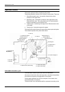
Recording cycle
One sheet of data for the front and back sides is taken out from the bit
map memory and the LED records electrostatic character patterns on the
photoconductor drum.
The printer starts a recording cycle when one sheet of data for the front
and back sides is accumulated in the bit map memory. This cycle outputs
one page.
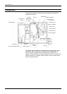
The electrostatic image on the drum is brushed by the developer which
applies toner to the image.
When the information transfer cycle for the next pages has been
completed in the bit map memory at the end of a recording cycle, the
next recording cycle starts immediately.
Transfer cycle
One sheet of information for the front and back sides is transferred from
the photoconductor drum to the paper.
Once information recorded on the photoconductor drum by a recording
cycle has reached the transfer position, a transfer cycle starts. If a
recording cycle is executed continuously for two pages or more, the
transfer cycle is also executed continuously.
If the recording cycle is interrupted, the paper feed pauses in the transfer
cycle (the paper is separated from the photoconductor drum).
A non-printing area is reserved to ensure complete transfer. This area is
6.35 mm in page printer mode.
Fusing cycle
Information transferred to printing paper is fused sequentially.
Once data-transferred paper has reached the fuser, a fusing cycle starts
automatically. After fusing, the paper is sent to the stacker.
Data-transferred paper cannot be taken out without fusing.