


CONFIGURATION
Page C-4 Xerox 495 Continuous Feed Duplex Printer Operator Guide
Configuration
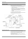
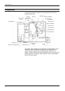
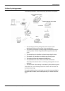
The following illustration shows the unit arrangement of this printer
looking from the front.
This printer can be divided into a mechanical unit section and a control
unit section. With a marking unit at the center, the mechanical unit
section consists of optical units, developing units, transfer units, a
hopper, a tractor assembly, a stacker, and auxiliary units. The control unit
section consists of a controller, power supplies, a main operator panel,
and a sub-operator panel.
Autoloader B
Roller Unit B[R1b]
Transfer Unit A
Touch Screen
Marking Unit A
Roller Unit A[R1a]
Optical Unit A
Toner Hopper A
Developer Unit A
Tractor Assembly
Hopper
Transfer
Unit B
Marking Unit B
Developing
Unit B
Fuser Power Supply (FV2)
Controller PC
Controller Shelf
Toner Hopper B
Stacker
Optical Unit B
Heater
Autoloader
A
Fuser A Fuser B