


BUS INTERFACE UNIT
3-34
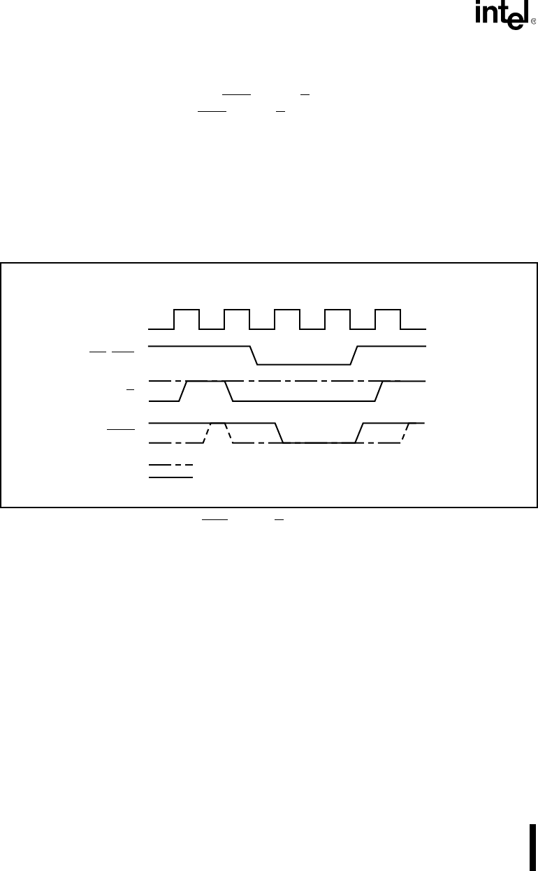
3.6.1 Buffering the Data Bus
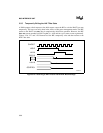
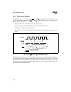
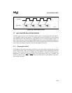
The BIU generates two control signals, DEN
and DT/R, to control bidirectional buffers or trans-
ceivers. The timing relationship of DEN
and DT/R is shown in Figure 3-30. The following con-
ditions require transceivers:
• The capacitive load on the address/data bus gets too large.
• The current load on the address/data bus exceeds device specifications.
• Additional V
OL
and V
OH
drive is required.
• A memory or I/O device cannot float its outputs in time to prevent bus contention, even at
reset.
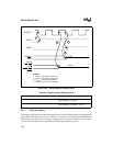
Figure 3-30. DEN and DT/R Timing Relationships
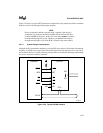
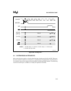
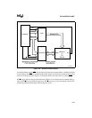
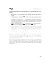
The circuit shown in Figure 3-31 illustrates how to use transceivers to buffer the address/data bus.
The connection between the processor and the transceiver is known as the local bus. A connection
between the transceiver and other memory or I/O devices is known as the buffered bus. A fully
buffered system has no devices attached to the local bus. A partially buffered system has devices
on both the local and buffered buses.
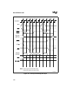
DT/R
RD,WR
CLKOUT
T1 T2 T3 T4
DEN
T1
Write Cycle Operation
Read Cycle Operation
A1094-A0