


CLOCK GENERATION AND POWER MANAGEMENT
5-2
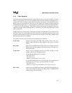
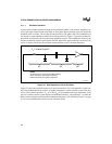
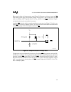
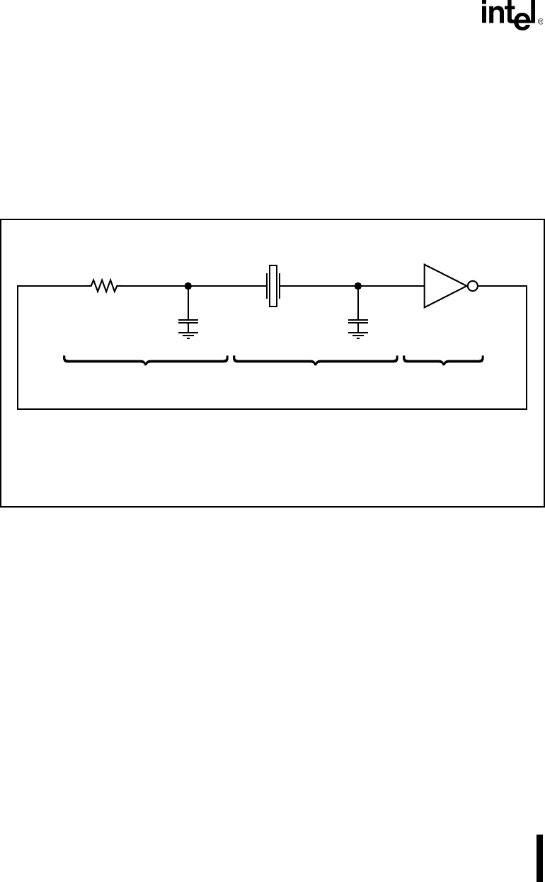
5.1.1.1 Oscillator Operation
A phase shift oscillator operates through positive feedback, where a non-inverted, amplified ver-
sion of the input connects back to the input. A 360° phase shift around the loop will sustain the
feedback in the oscillator. The on-chip inverter provides a 180° phase shift. The combination of
the inverter’s output impedance and the first load capacitor (see Figure 5-2) provides another 90°
phase shift. At resonance, the crystal becomes primarily resistive. The combination of the crystal
and the second load capacitor provides the final 90° phase shift. Above and below resonance, the
crystal is reactive and forces the oscillator back toward the crystal’s nominal frequency.
Figure 5-2. Ideal Operation of Pierce Oscillator
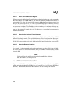
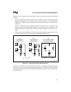
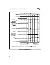
Figure 5-3 shows the actual microprocessor crystal connections. For low frequencies, crystal ven-
dors offer fundamental mode crystals. At higher frequencies, a third overtone crystal is the only
choice. The external capacitors, C
X1
at X1 and C
X2
at X2, together with stray capacitance, form
the load. A third overtone crystal requires an additional inductor L
1
and capacitor C
1
to select the
third overtone frequency and reject the fundamental frequency. See “Selecting Crystals” on page
5-5 for a more detailed discussion of crystal vibration modes.
90˚ 180˚90˚
NOTE:
At resonance, the crystal is essentially resistive.
Above resonance, the crystal is inductive.
Below resonance, the crystal is capacitive.
Z = Inverter Output Z
0
A1125-0A