


8-23
INTERRUPT CONTROL UNIT
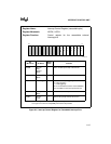
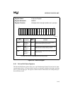
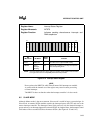
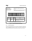
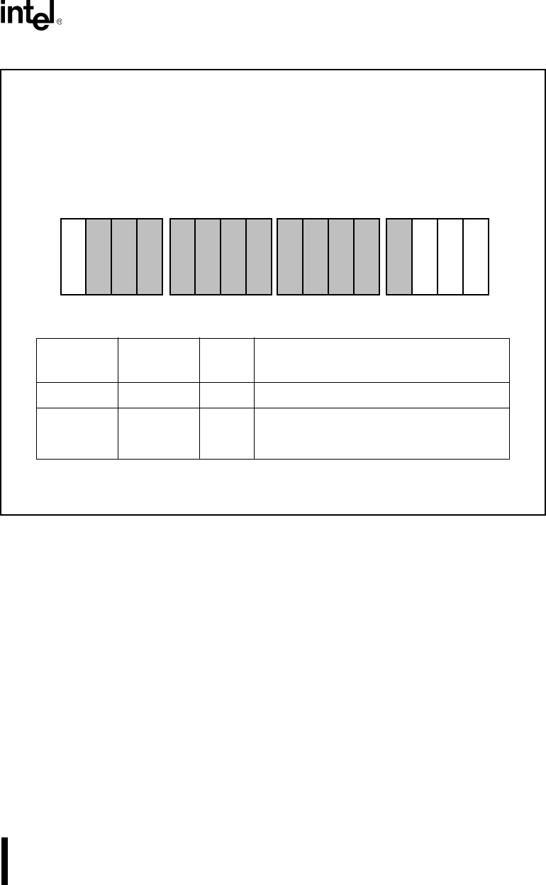
Figure 8-14. Interrupt Status Register
NOTE
Do not write to the DHLT bit while Timer/Counter Unit interrupts are enabled.
A conflict with the internal use of the register may cause incorrect processing
of timer interrupts.
The DHLT bit does not function when the interrupt controller is in slave mode.
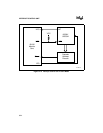
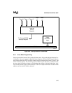
8.5 SLAVE MODE
Although Master mode is the most common, Slave mode is useful in larger system designs. In
Slave mode, an external 8259A module controls the interrupt input to the CPU and acts as the
master interrupt controller. The Interrupt Control Unit processes only the internal interrupt re-
quests and acts as an interrupt input to the external 8259A. In simplest terms, the Interrupt Control
Unit behaves like a cascaded 8259A to the master 8259A. (See Figures 8-15 and 8-16.)
Register Name: Interrupt Status Register
Register Mnemonic: INTSTS
Register Function: Indicates pending shared-source interrupts and
DMA suspension
Bit
Mnemonic
Bit Name
Reset
State
Function
DHLT DMA Halt 0 This bit is set to suspend DMA activity.
TMR2:0 Timer
Interrupt
Pending
000 A bit is set to indicate a pending interrupt from
the corresponding timer.
NOTE: Reserved register bits are shown with gray shading. Reserved bits must be written
to a logic zero to ensure compatibility with future Intel products.
A1193-A0
15 0
T
M
R
0
T
M
R
2
D
H
L
T
T
M
R
1