


INTERRUPT CONTROL UNIT
8-2
Interrupts eliminate the need for polling by signalling the CPU that a peripheral device requires
servicing. The CPU then stops executing the main task, saves its state and transfers execution to
the peripheral-servicing code (the interrupt handler). At the end of the interrupt handler, the
CPU’s original state is restored and execution continues at the point of interruption in the main
task.
8.2 MASTER MODE
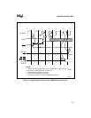
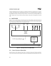
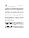
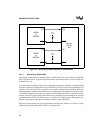
Figure 8-1 shows a block diagram of the Interrupt Control Unit in Master mode. In this mode, the
ICU processes all interrupt requests, both external and internal. The three timer interrupt requests
share a single input, while the others are supported directly.
Figure 8-1. Interrupt Control Unit in Master Mode
8.2.1 Generic Functions in Master Mode
Several functions of the Interrupt Control Unit are common among most interrupt controllers.
This section describes how those generic functions are implemented in the Interrupt Control Unit.
INT0 INT1 INT2 INT3
Interrupt
Priority
Resolver
Timer 0 Timer 1 Timer 2
DMA
0
DMA
1
Vector
Generation
Logic
To CPU Interrupt Request
F - Bus
A1506-A0