


D-3
INSTRUCTION SET OPCODES AND CLOCK CYCLES
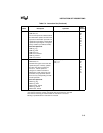
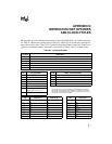
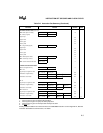
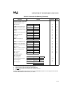
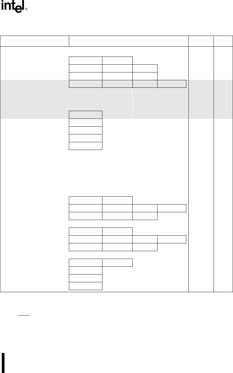
DATA TRANSFER INSTRUCTIONS (Continued)
LEA = Load EA to register 1 0 0 0 1 1 0 1 mod reg r/m 6
LDS = Load pointer to DS 1 1 0 0 0 1 0 1 mod reg r/m (mod ?11) 18
LES = Load pointer to ES 1 1 0 0 0 1 0 0 mod reg r/m (mod ?11) 18
ENTER = Build stack frame 1 1 0 0 1 0 0 0 data-low data-high L
L = 0
15
L = 1
25
L > 1
22+16(n-1)
LEAVE = Tear down stack frame 1 1 0 0 1 0 0 1 8
LAHF = Load AH with flags 1 0 0 1 1 1 1 1 2
SAHF = Store AH into flags 1 0 0 1 1 1 1 0 3
PUSHF = Push flags 1 0 0 1 1 1 0 0 9
POPF = Pop flags 1 0 0 1 1 1 0 1 8
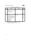
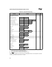
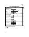
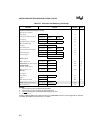
ARITHMETIC INSTRUCTIONS
ADD = Add
reg/memory with register to either
0 0 0 0 0 0 d w mod reg r/m 3/10
immediate to register/memory
1 0 0 0 0 0 s w mod 000 r/m data data if sw=01 4/16
immediate to accumulator
0 0 0 0 0 1 0 w data data if w=1 3/4 (1)
ADC = Add with carry
reg/memory with register to either
0 0 0 1 0 0 d w mod reg r/m 3/10
immediate to register/memory
1 0 0 0 0 0 s w mod 010 r/m data data if sw=01 4/16
immediate to accumulator
0 0 0 1 0 1 0 w data data if w=1 3/4 (1)
INC = Increment
register/memory
1 1 1 1 1 1 1 w mod 000 r/m 3/15
register
0 1 0 0 0 reg 3
AAA = ASCII adjust for addition 0 0 1 1 0 1 1 1 8
DAA = Decimal adjust for addition 0 0 1 0 0 1 1 1 4
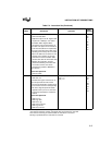
Table D-2. Instruction Set Summary (Continued)
Function Format Clocks Notes
NOTES:
1. Clock cycles are given for 8-bit/16-bit operations.
2. Clock cycles are given for jump not taken/jump taken.
3. Clock cycles are given for interrupt taken/interrupt not taken.
4. If TEST
= 0
Shading indicates additions and enhancements to the 8086/8088 instruction set. See Appendix A, “80C186
Instruction Set Additions and Extensions,” for details.