


TIMER/COUNTER UNIT
9-8
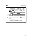
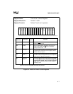
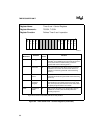
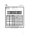
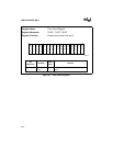
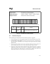
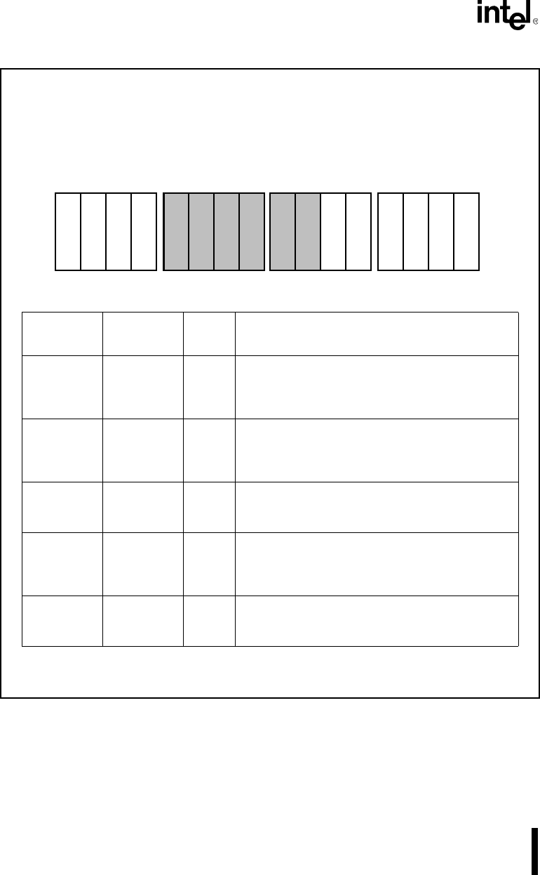
Figure 9-5. Timer 0 and Timer 1 Control Registers (Continued)
Register Name: Timer 0 and 1 Control Registers
Register Mnemonic: T0CON, T1CON
Register Function: Defines Timer 0 and 1 operation.
Bit
Mnemonic
Bit Name
Reset
State
Function
RTG Retrigger X This bit specifies the action caused by a low-to-high
transition on the TMR INx input. Set RTG to reset the
count; clear RTG to enable counting. This bit is
ignored with external clocking (EXT=1).
P Prescaler X Set to increment the timer when Timer 2 reaches its
maximum count. Clear to increment the timer at ¼
CLKOUT. This bit is ignored with external clocking
(EXT=1).
EXT External
Clock
X Set to use external clock; clear to use internal clock.
The RTG and P bits are ignored with external clocking
(EXT set).
ALT Alternate
Compare
Register
X This bit controls whether the timer runs in single or
dual maximum count mode (see Figure 9-4 on page
9-6). Set to specify dual maximum count mode; clear
to specify single maximum count mode.
CONT Continuous
Mode
X Set to cause the timer to run continuously. Clear to
disable the counter (clear the EN bit) after each
counting sequence.
NOTE: Reserved register bits are shown with gray shading. Reserved bits must be written to a
logic zero to ensure compatibility with future Intel products.
15 0
C
O
N
T
A
L
T
E
X
T
R
T
G
M
C
PR
I
U
I
N
T
I
N
H
E
N
A1297-0A