


9-11
TIMER/COUNTER UNIT
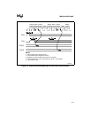
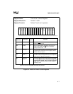
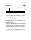
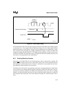
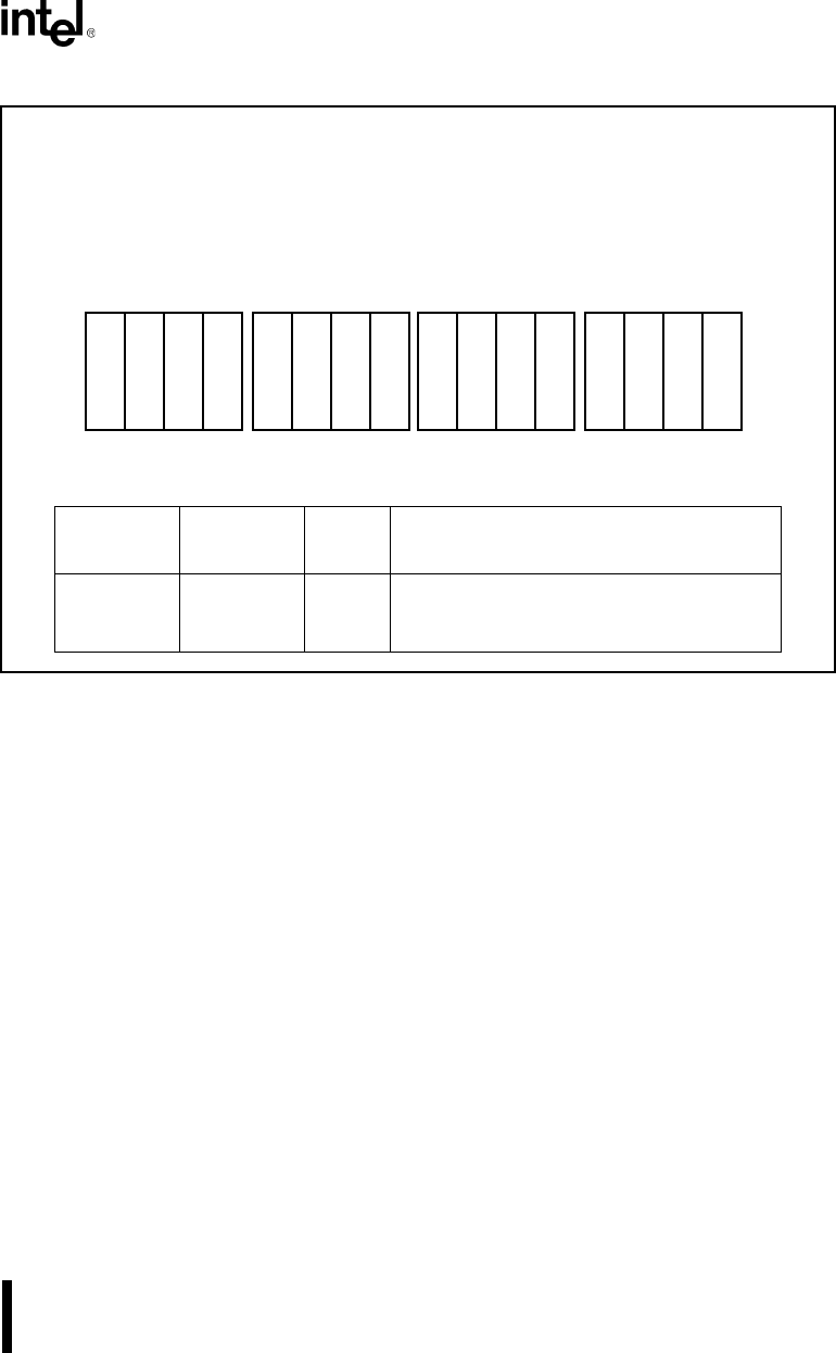
Figure 9-8. Timer Maxcount Compare Registers
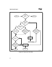
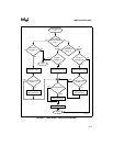
9.2.1 Initialization Sequence
When initializing the Timer/Counter Unit, the following sequence is suggested:
1. If timer interrupts will be used, program interrupt vectors into the Interrupt Vector Table.
2. Clear the Timer Count register. This must be done before the timer is enabled because
the count register is undefined at reset. Clearing the count register ensures that counting
begins at zero.
3. Write the desired maximum count value to the Timer Maxcount Compare register. For
dual maximum count mode, write a value to both Maxcount Compare A and B.
4. Program the Timer Control register to enable the timer. When using Timer 2 to prescale
another timer, enable Timer 2 last. If Timer 2 is enabled first, it will be at an unknown
point in its timing cycle when the timer to be prescaled is enabled. This results in an
unpredictable duration of the first timing cycle for the prescaled timer.
Register Name: Timer Maxcount Compare Register
Register Mnemonic: T0CMPA, T0CMPB, T1CMPA, T1CMPB, T2CMPA
Register Function: Contains timer maximum count value.
Bit
Mnemonic
Bit Name
Reset
State
Function
TC15:0 Timer
Compare
Value
XXXXH Contains the maximum value a timer will count
to before resetting its Count register to zero.
15 0
T
C
1
3
T
C
1
4
T
C
1
5
T
C
1
2
T
C
9
T
C
1
0
T
C
1
1
T
C
8
T
C
5
T
C
6
T
C
7
T
C
4
T
C
1
T
C
2
T
C
3
T
C
0
A1300-0A