


3-17
BUS INTERFACE UNIT
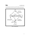
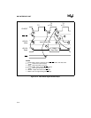
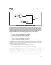
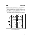
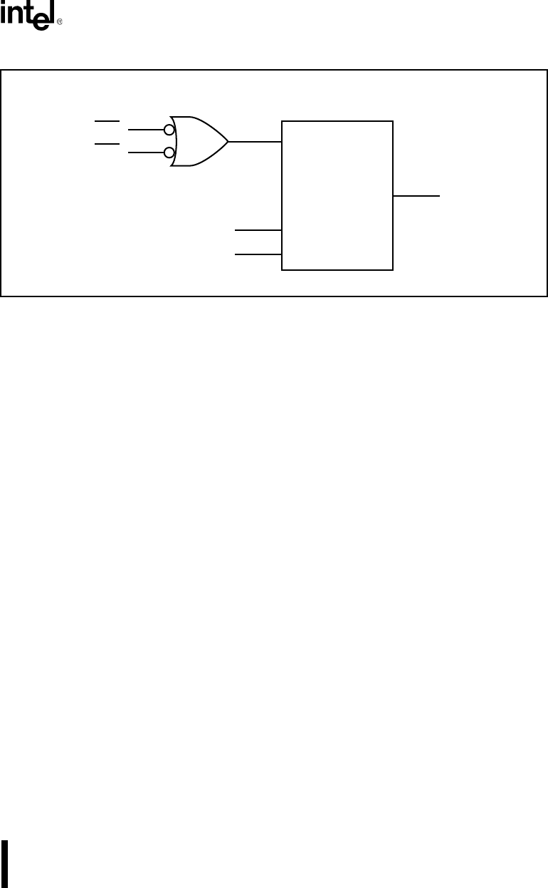
Figure 3-16. Generating a Normally Ready Bus Signal
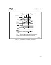
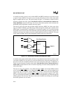
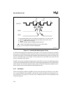
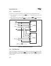
The ARDY input has two major timing concerns that can affect whether a normally ready or nor-
mally not-ready signal may be required. Two latches capture the state of the ARDY input (see
Figure 3-14 on page 3-15). The first latch captures ARDY on the phase 2 clock edge. The second
latch captures ARDY and the result of first latch on the phase 1 clock edge. The following items
define the requirements of the ARDY input to meet ready or not-ready bus conditions.
• The bus is ready if both of these two conditions are true:
— ARDY is active prior to the phase 2 clock edge, and
— ARDY remains active after the phase 1 clock edge.
• The bus is not-ready if either of these two conditions is true:
— ARDY is inactive prior to the phase 2 clock edge, or
— ARDY is inactive prior to the phase 1 clock edge.
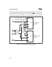
A single latch captures the state of the SRDY input (see Figure 3-14 on page 3-15). SRDY must
be valid by the phase 1 clock edge. The following items define the requirements of the SRDY
input to meet ready or not-ready bus conditions.
• The bus is ready if SRDY is active prior to the phase 1 clock edge.
• The bus is not-ready if SRDY is inactive prior to the phase 1 clock edge.
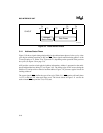
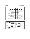
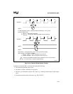
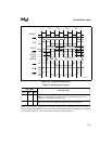
A normally not-ready system must generate a valid ARDY input at phase 2 of T2 or a valid SRDY
input at phase 1 of T3 to prevent wait states. If it cannot, then running without wait states requires
a normally ready system. Figure 3-17 illustrates the timing necessary to prevent wait states in a
normally not-ready system. Figure 3-17 also shows how to terminate a bus cycle with wait states
in a normally not-ready system.
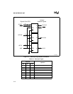
Enable
Out
READY
Wait State Module
Load
Clock
ALE
CLKOUT
CS1
CS2
A1081-0A