


8-25
INTERRUPT CONTROL UNIT
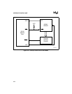
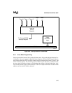
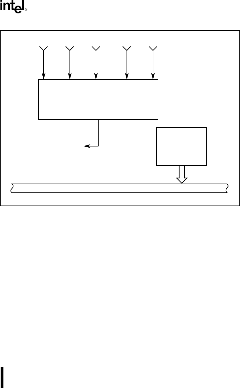
Figure 8-16. Interrupt Sources in Slave Mode
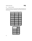
8.5.1 Slave Mode Programming
Some registers differ between Slave mode and Master mode. Slave mode adds the Interrupt Vec-
tor Register; it does not support the Poll, Poll Status Registers, INT3 and INT2 Control registers;
and it replaces the Timer, INT1 and INT0 Control registers with individual Timer 0, Timer 1, and
Timer 2 Control registers. The remaining registers retain the same functions as in Master mode;
however, some bit positions change to accommodate the addition of the individual timer inter-
rupts and the deletion of the external interrupts. Table 8-4 compares the Master and Slave mode
registers and lists their PCB offset addresses.
Interrupt
Priority
Resolver
Timer 0 Timer 1 Timer 2
DMA
0
DMA
1
Vector
Generation
Logic
To External 8259A
Interrupt Request
F - Bus
A1195-A0