


6-21
CHIP-SELECT UNIT
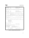
Example 6-1. Initializing the Chip-Select Unit (Continued)
DRAM_BASE EQU 256 ;window start address in Kbytes
DRAM_SIZE EQU 256 ;window size in Kbytes
DRAM_WAIT EQU 0 ;wait states
DRAM_RDY EQU INTRDY ;ignore bus ready
;The MPCS register is used to program both the MCS and PCS chip-selects.
;Below are the equates for the I/O peripherals (also used to program the PACS
;register.
IO_WAIT EQU 4 ;IO wait states
IO_RDY EQU INTRDY ;ignore bus ready
PCS_SPACE EQU IO ;put PCS# chip-selects in I/O space
PCS_FUNC EQU ALLPCS ;generate PCS5# and PCS6#
;The MMCS and MPCS register values are calculated using the above system
;constraints and the equations below:
MMCS_VAL EQU (DRAM_BASE SHL 6) OR (001F8H) OR (DRAM_RDY) OR (DRAM_WAIT)
MPCS_VAL EQU (DRAM_SIZE SHL 5) OR (08038H) OR (PCS_SPACE) OR (PCS_FUNC) OR
& (IO_RDY) OR (IO_WAIT)
;I/O is selected using the PCS0# chip-select. Wait states assume operation at
;16 MHz. For this example, the Floppy Disk Controller is connected to PCS2# and
;PCS1# provides the DACK signal.
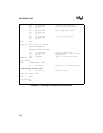
IO_BASE EQU 1 ;I/O start address in Kbytes
;The PACS register value is calculated using the above system constraints and
;the equation below.
PACS_VAL EQU (IO_BASE SHL 6) OR (0038H) OR (IO_RDY) OR (IO_WAIT)
;The following statements define the default assumptions for segment locations.
ASSUME CS:CODE
ASSUME DS:DATA
ASSUME SS:DATA
ASSUME ES:DATA
CODE SEGMENT PUBLIC 'CODE'
;
;Entry point on power-up
;
FW_START LABEL FAR ;forces far jump
CLI ;disable interrupts
;Place register initialization code here
;
;Set up chip-selects.
;UCS - EPROM Select (initialized during POWER_ON code)
;LCS - SRAM Select (set to SRAM size)
;PCS - I/O Select (PCS1:0 to support floppy)
;MCS - DRAM Select (set to DRAM size)
mov dx, LMCS_REG ;set up LMCS register
mov ax, LMCS_VAL
out dx, al ;remember that byte writes are OK