


7-1
CHAPTER 7
REFRESH CONTROL UNIT
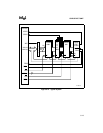
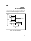
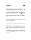
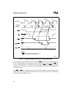
The Refresh Control Unit (RCU) simplifies dynamic memory controller design with its integrat-
ed address and clock counters. Figure 7-1 shows the relationship between the Bus Interface Unit
and the Refresh Control Unit. Integrating the Refresh Control Unit into the processor allows an
external DRAM controller to use chip-selects, wait state logic and status lines.
Figure 7-1. Refresh Control Unit Block Diagram
Refresh Clock
Interval Register
9-Bit Down
Counter
Refresh Control
Register
Refresh Base
Address Register
Refresh Address
Register
Refresh Request
Refresh Acknowledge
BIU
Interface
9-Bit Address Counter
F-Bus
CPU
Clock
20-Bit
Refresh Address
7
13
CLR
REQ
A1539-01