


CHIP-SELECT UNIT
6-16
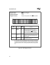
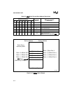
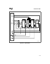
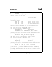
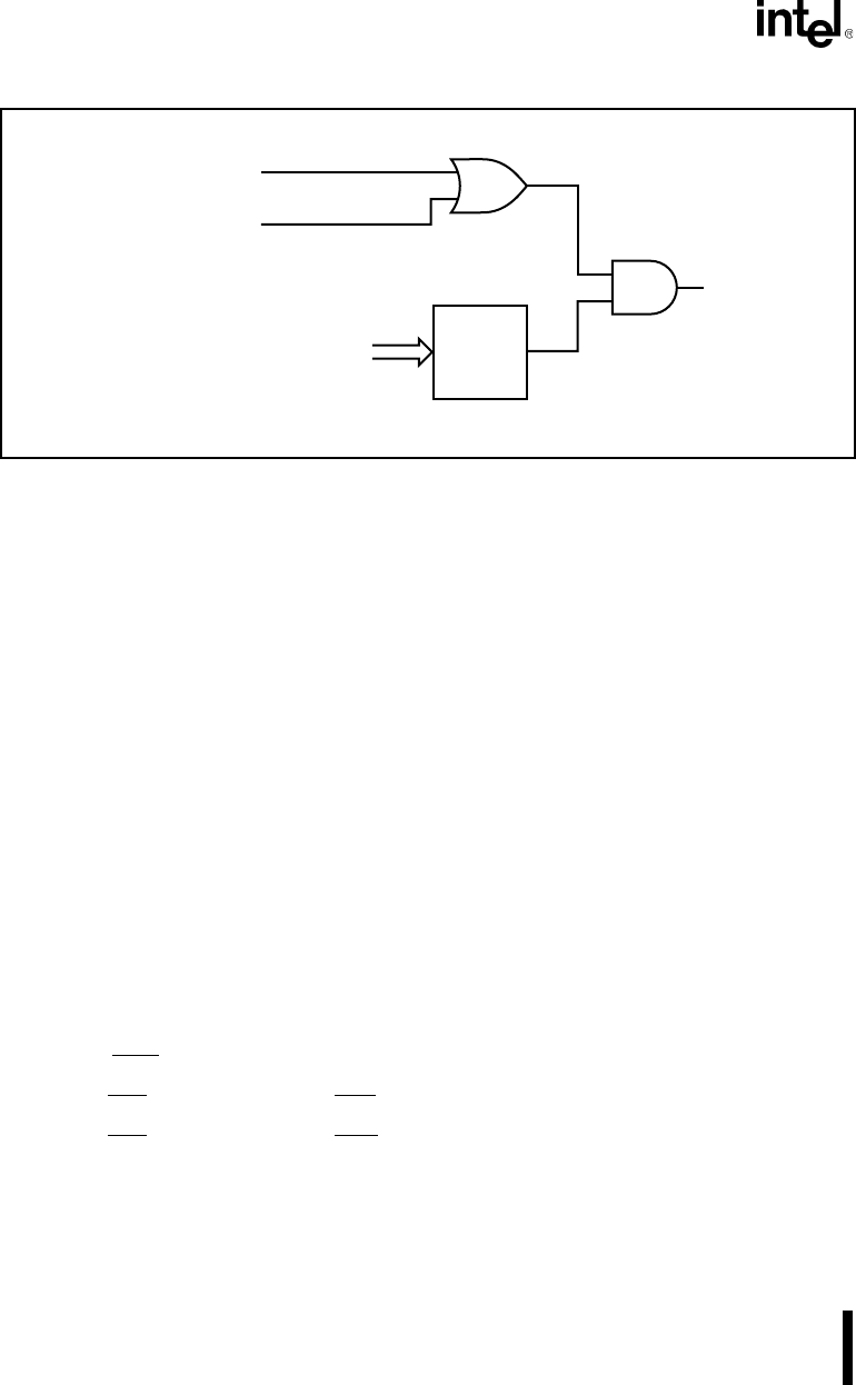
Figure 6-11. Wait State and Ready Control Functions
The R2 control bit determines whether the bus cycle completes normally (requires bus ready) or
unconditionally (ignores bus ready). The R1:0 bits define the number of wait states to insert into
the bus cycle. For devices requiring three or fewer wait states, you can set R2 (ignore bus ready)
and program R1:0 with the number of required wait states. For devices that may require more than
three wait states, you must clear R2 (require bus ready).
A bus cycle with wait states automatically inserted cannot be shortened. A bus cycle that ignores
bus ready cannot be lengthened.
6.4.4 Overlapping Chip-Selects
The Chip-Select Unit activates all enabled chip-selects programmed to cover the same physical
address space. This is true if any portion of the chip-selects’ address ranges overlap (i.e., chip-
selects’ ranges do not need to overlap completely to all go active). There are various reasons for
overlapping chip-selects. For example, a system might have a need for overlapping a portion of
read-only memory with read/write memory or copying data to two devices simultaneously.
If overlapping chip-selects do not have identical wait state and bus ready programming, the Chip-
Select Unit uses the following priority scheme:
1. If any MCS
chip-select is active, it uses the R2:0 bits in the MPCS register.
2. If the PCS
chip-selects overlap LCS, it uses the R2:0 bits in the LMCS register.
3. If the PCS
chip-selects overlap UCS, it uses the R2:0 bits in the UMCS register.
Wait State Value (R1:0)
READY
R2 Control Bit
Wait
State
Counter
BUS READY
Wait
State
Ready
A1137-0A