


8-11
INTERRUPT CONTROL UNIT
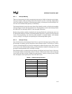
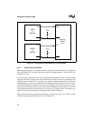
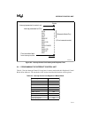
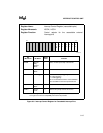
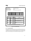
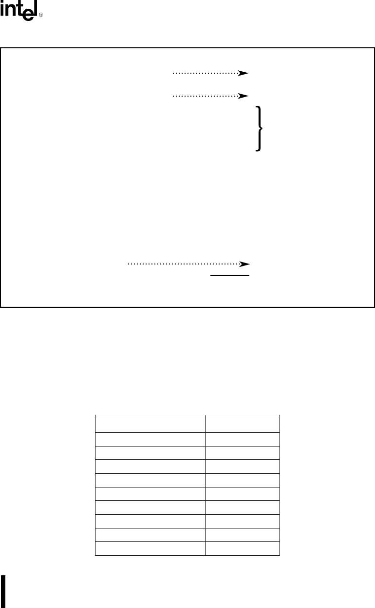
Figure 8-3. Interrupt Control Unit Latency and Response Time
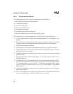
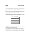
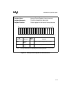
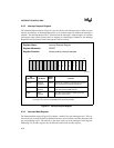
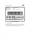
8.4 PROGRAMMING THE INTERRUPT CONTROL UNIT
Table 8-3 lists the Interrupt Control Unit registers in master mode with their Peripheral Control
Block offset addresses. The remainder of this section describes the functions of the registers.
Table 8-3. Interrupt Control Unit Registers in Master Mode
Register Name Offset Address
INT3 Control 3EH
INT2 Control 3CH
INT1 Control 3AH
INT0 Control 38H
DMA0 Control 34H
DMA1 Control 36H
Timer Control 32H
Interrupt Status 30H
Interrupt Request 2EH
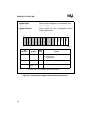
Clocks
5
4
2
4
5
4
3
4
4
4
3
4
4
5
Total 55
First instruction fetch
from interrupt routine
INTA
IDLE
INTA
IDLE
READ IP
IDLE
READ CS
IDLE
PUSH FLAGS
IDLE
PUSH CS
PUSH IP
IDLE
Interrupt presented to control unit
Interrupt presented to CPU
(5 if not cascade mode)
Cascade Mode Only
A1212-A0