


D-1
APPENDIX D
INSTRUCTION SET OPCODES
AND CLOCK CYCLES
This appendix provides reference information for the 80C186 Modular Core family instruction
set. Table D-1 defines the variables used in Table D-2, which lists the instructions with their for-
mats and execution times. Table D-3 is a guide for decoding machine instructions. Table D-4 is
a guide for encoding instruction mnemonics, and Table D-5 defines Table D-4 abbreviations.
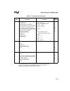
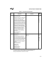
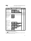
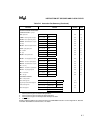
Table D-1. Operand Variables
Variable Description
mod
mod
and
r/m
determine the Effective Address (EA).
r/m
r/m
and
mod
determine the Effective Address (EA).
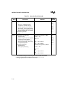
reg
reg
represents a register.
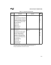
MMM
MMM
and
PPP
are opcodes to the math coprocessor.
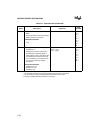
PPP
PPP
and
MMM
are opcodes to the math coprocessor.
TTT
TTT
defines which shift or rotate instruction is executed.
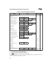
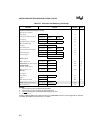
r/m EA Calculation mod Effect on EA Calculation
0 0 0 (BX) + (SI) + DISP 0 0 if r/m ≠ 110, DISP = 0; disp-low and disp-high are absent
0 0 1 (BX) + (DI) + DISP 0 0 if r/m = 110, EA = disp-high:disp-low
0 1 0 (BP) + (SI) + DISP 0 1 DISP = disp-low, sign-extended to 16 bits; disp-high is absent
0 1 1 (BP) + (DI) + DISP 1 0 DISP = disp-high:disp-low
1 0 0 (SI) + DISP 1 1 r/m is treated as a reg field
1 0 1 (DI) + DISP DISP follows the second byte of the instruction (before any required data).
Physical addresses of operands addressed by the BP register are computed
using the SS segment register. Physical addresses of destination operands of
string primitives (addressed by the DI register) are computed using the ES seg-
ment register, which cannot be overridden.
1 1 0 (BP) + DISP, if mod ≠ 00
disp-high:disp-low, if mod =00
1 1 1 (BX) + DISP
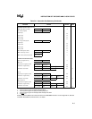
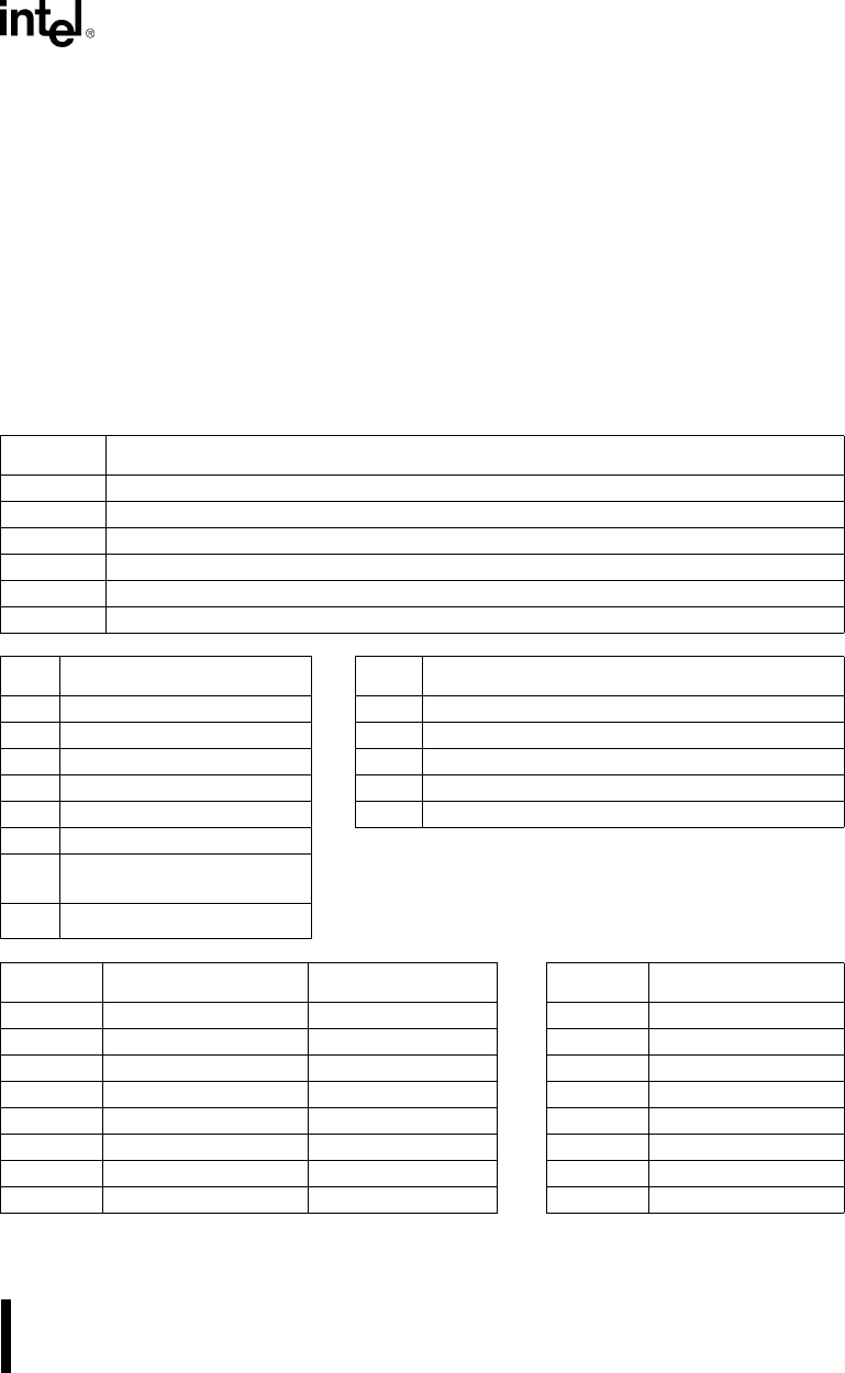
reg 16-bit (w=1) 8-bit (w=0) TTT Instruction
0 0 0 AX AL 0 0 0 ROL
0 0 1 CX CL 0 0 1 ROR
0 1 0 DX DL 0 1 0 RCL
0 1 1 BP BL 0 1 1 RCR
1 0 0 SP AH 1 0 0 SHL/SAL
1 0 1 BP CH 1 0 1 SHR
1 1 0 SI DH 1 1 0 —
1 1 1 DI BH 1 1 1 SAR