


BUS INTERFACE UNIT
3-10
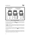
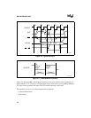
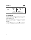
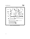
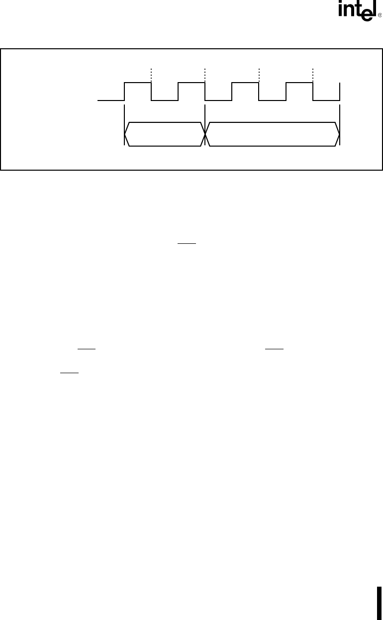
Figure 3-9. T-State and Bus Phases
3.4.1 Address/Status Phase
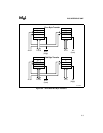
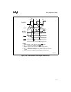
Figure 3-10 shows signal timing relationships for the address/status phase of a bus cycle. A bus
cycle begins with the transition of ALE and S2:0
. These signals transition during phase 2 of the
T-state just prior to T1. Either T4 or TI precedes T1, depending on the operation of the previous
bus cycle (see Figure 3-8 on page 3-9).
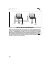
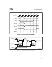
ALE provides a strobe to latch physical address information. Address is presented on the multi-
plexed address/data bus during T1 (see Figure 3-10). The falling edge of ALE occurs during the
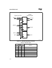
middle of T1 and provides a strobe to latch the address. Figure 3-11 presents a typical circuit for
latching addresses.
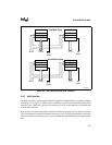
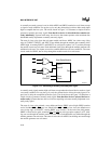
The status signals (S2:0
) define the type of bus cycle (Table 3-1). S2:0 remain valid until phase
1 of T3 (or the last TW, when wait states occur). The circuit shown in Figure 3-11 can also be
used to extend S2:0
beyond the T3 (or TW) state.
T4
or TI
T1 T2
T3
or TW
CLKOUT
Address/
Status Phase
Data Phase
T4
or TI
A1113-0A