


D-9
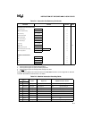
INSTRUCTION SET OPCODES AND CLOCK CYCLES
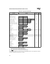
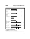
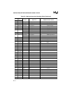
PROCESSOR CONTROL INSTRUCTIONS
CLC = Clear carry 1 1 1 1 1 0 0 0 2
CMC = Complement carry 1 1 1 1 0 1 0 1 2
STC = Set carry 1 1 1 1 1 0 0 1 2
CLD = Clear direction 1 1 1 1 1 1 0 0 2
STD = Set direction 1 1 1 1 1 1 0 1 2
CLI = Clear interrupt 1 1 1 1 1 0 1 0 2
STI = Set interrupt 1 1 1 1 1 0 1 1 2
HLT = Halt 1 1 1 1 0 1 0 0 2
WAIT = Wait 1 0 0 1 1 0 1 1 6 (4)
LOCK = Bus lock prefix 1 1 1 1 0 0 0 0 2
ESC = Math coprocessor escape 1 1 0 1 1 M M M mod PPP r/m 6
NOP = No operation 1 0 0 1 0 0 0 0 3
SEGMENT OVERRIDE PREFIX
CS
0 0 1 0 1 1 1 0 2
SS
0 0 1 1 0 1 1 0 2
DS
0 0 1 1 1 1 1 0 2
ES
0 0 1 0 0 1 1 0 2
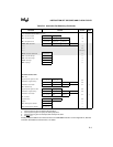
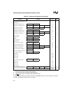
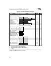
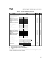
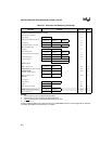
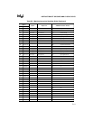
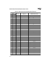
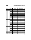
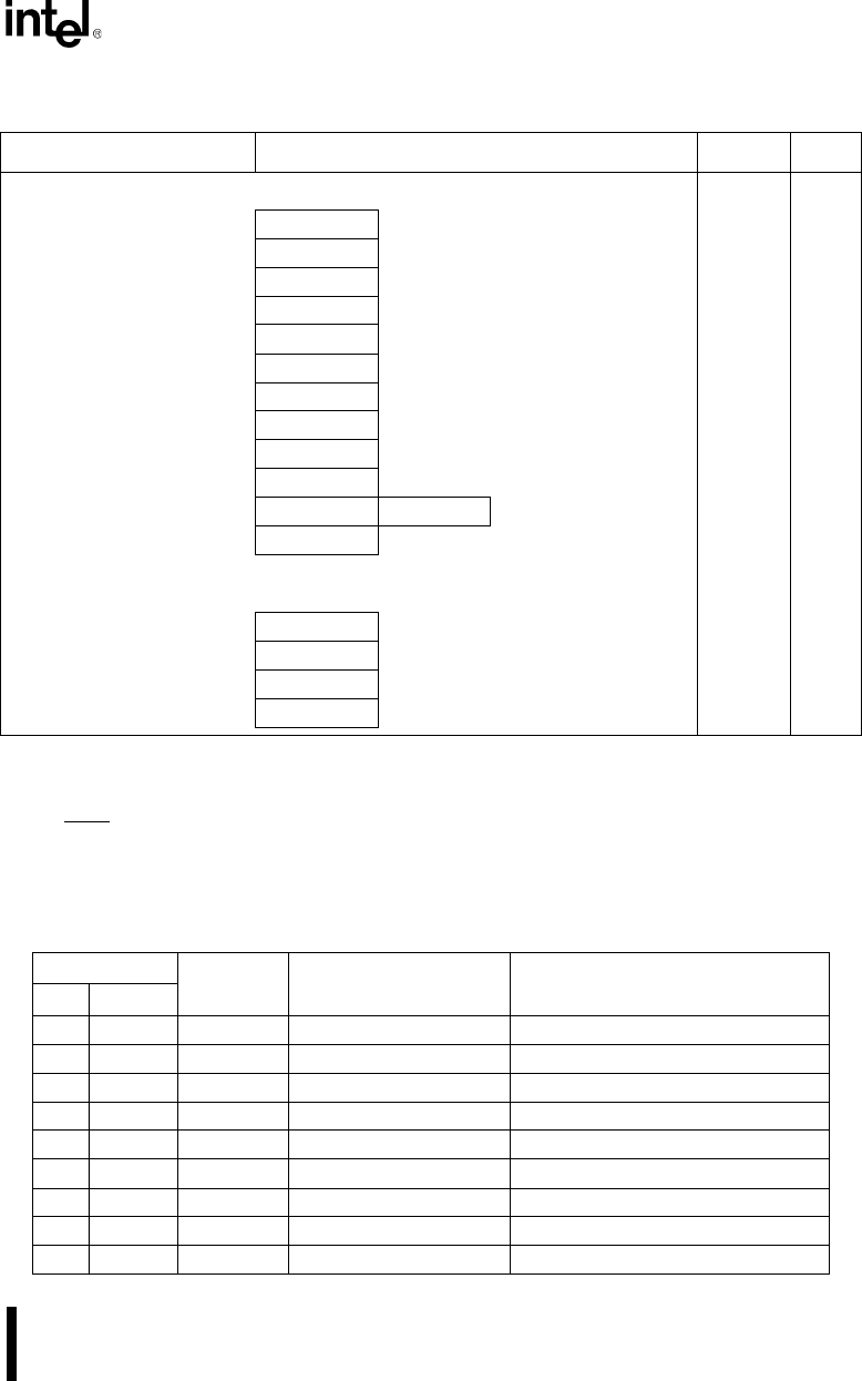
Table D-3. Machine Instruction Decoding Guide
Byte 1
Byte 2 Bytes 3–6 ASM-86 Instruction Format
Hex Binary
00 0000 0000 mod reg r/m (disp-lo),(disp-hi) add reg8/mem8, reg8
01 0000 0001 mod reg r/m (disp-lo),(disp-hi) add reg16/mem16,reg16
02 0000 0010 mod reg r/m (disp-lo),(disp-hi) add reg8,reg8/mem8
03 0000 0011 mod reg r/m (disp-lo),(disp-hi) add reg16,reg16/mem16
04 0000 0100 data-8 add AL,immed8
05 0000 0101 data-lo data-hi add AX,immed16
06 0000 0110 push ES
07 0000 0111 pop ES
08 0000 0100 mod reg r/m (disp-lo),(disp-hi) or reg8/mem8,reg8
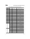
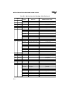
Table D-2. Instruction Set Summary (Continued)
Function Format Clocks Notes
NOTES:
1. Clock cycles are given for 8-bit/16-bit operations.
2. Clock cycles are given for jump not taken/jump taken.
3. Clock cycles are given for interrupt taken/interrupt not taken.
4. If TEST
= 0
Shading indicates additions and enhancements to the 8086/8088 instruction set. See Appendix A, “80C186
Instruction Set Additions and Extensions,” for details.