


BUS INTERFACE UNIT
3-16
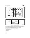
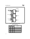
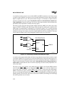
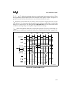
A normally not-ready system is one in which ARDY and SRDY remain low at all times except
to signal a ready condition. For any bus cycle, only the selected device drives either ready input
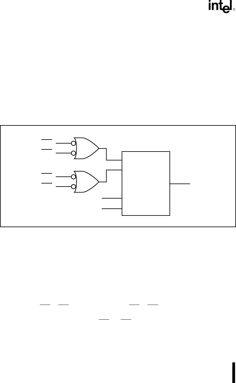
high to complete the bus cycle. The circuit shown in Figure 3-15 illustrates a simple circuit to
generate a normally not-ready signal. Note that if no device is selected the bus remains not-
ready indefinitely. Systems with many slow devices that cannot operate at the maximum bus
bandwidth usually implement a normally not-ready signal.
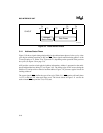
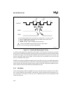
The start of a bus cycle clears the wait state module and forces ARDY low. After every rising
edge of CLKOUT, INPUT1 and INPUT2 are shifted through the module and eventually drive
ARDY high. Assuming INPUT1 and INPUT2 are valid prior to phase 2 of T2, no delay through
the module causes one wait state. Each additional clock delay through the module generates one
additional wait state. Two inputs are used to establish different wait state conditions. The same
circuit works for SRDY, but no delay through the module results in no wait states.
Figure 3-15. Generating a Normally Not-Ready Bus Signal
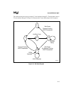
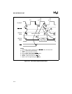
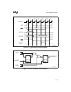
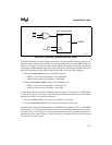
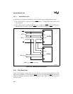
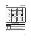
A normally ready signal remains high at all times except when the selected device needs to signal
a not-ready condition. For any bus cycle, only the selected device drives the ready input (or in-
puts) low to delay the completion of the bus cycle. The circuit shown in Figure 3-16 illustrates a
simple circuit to generate a normally ready signal. Note that if no device is selected the bus re-
mains ready. Systems that have few or no devices requiring wait states usually implement a nor-
mally ready signal.
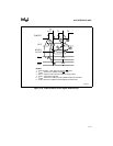
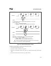
The start of a bus cycle preloads a zero shifter and forces SRDY active (high). SRDY remains
active if neither CS1
or CS2 goes low. Should either CS1 or CS2 go low, zeros are shifted out on
every rising edge of CLKOUT, causing SRDY to go inactive. At the end of the shift pattern,
SRDY is forced active again. Assuming CS1
and CS2 are active just prior to phase 2 of T2, shift-
ing one zero through the module causes one wait state. Each additional zero shifted through the
module generates one wait state. The same circuit works for ARDY, but shifting one zero through
the module generates two wait states.
Input 1
Out
READY
Wait State Module
Input 2
Clear
Clock
ALE
CLKOUT
CS1
CS2
CS3
CS4
A1080-0A