


2-9
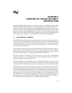
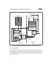
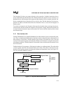
OVERVIEW OF THE 80C186 FAMILY ARCHITECTURE
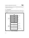
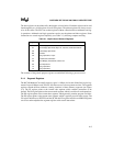
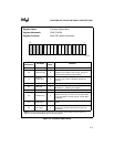
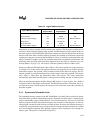
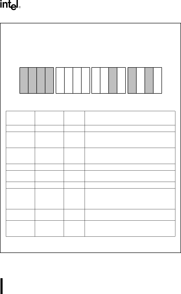
Figure 2-5. Processor Status Word
Register Name: Processor Status Word
Register Mnemonic: PSW (FLAGS)
Register Function: Posts CPU status information.
Bit
Mnemonic
Bit Name
Reset
State
Function
OF Overflow Flag 0 If OF is set, an arithmetic overflow has occurred.
DF Direction Flag 0
If DF is set, string instructions are processed high
address to low address. If DF is clear, strings are
processed low address to high address.
IF
Interrupt
Enable Flag
0
If IF is set, the CPU recognizes maskable interrupt
requests. If IF is clear, maskable interrupts are
ignored.
TF Trap Flag 0 If TF is set, the processor enters single-step mode.
SF Sign Flag 0
If SF is set, the high-order bit of the result of an
operation is 1, indicating it is negative.
ZF Zero Flag 0 If ZF is set, the result of an operation is zero.
AF Auxiliary Flag 0
If AF is set, there has been a carry from the low
nibble to the high or a borrow from the high nibble
to the low nibble of an 8-bit quantity. Used in BCD
operations.
PF Parity Flag 0
If PF is set, the result of an operation has even
parity.
CF Carry Flag 0
If CF is set, there has been a carry out of, or a
borrow into, the high-order bit of the result of an
instruction.
NOTE: Reserved register bits are shown with gray shading. Reserved bits must be written to a
logic zero to ensure compatibility with future Intel products.
15 0
O
F
D
F
I
F
T
F
S
F
Z
F
A
F
P
F
C
F
A1035-0A