


10-11
DIRECT MEMORY ACCESS UNIT
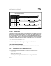
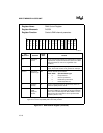
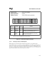
Two 16-bit Peripheral Control Block registers define each of the 20-bit pointers. Figures 10.7 and
10.8 show the layout of the DMA Source Pointer address registers, and Figures 10.9 and 10.10
show the layout of the DMA Destination Pointer address registers. The DSA19:16 and
DDA19:16 (high-order address bits) are driven on the bus even if I/O transfers have been pro-
grammed. When performing I/O transfers within the normal 64K I/O space only, the high-order
bits in the pointer registers must be cleared.
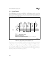
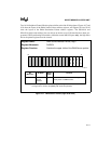
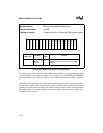
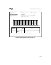
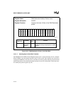
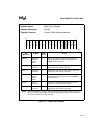
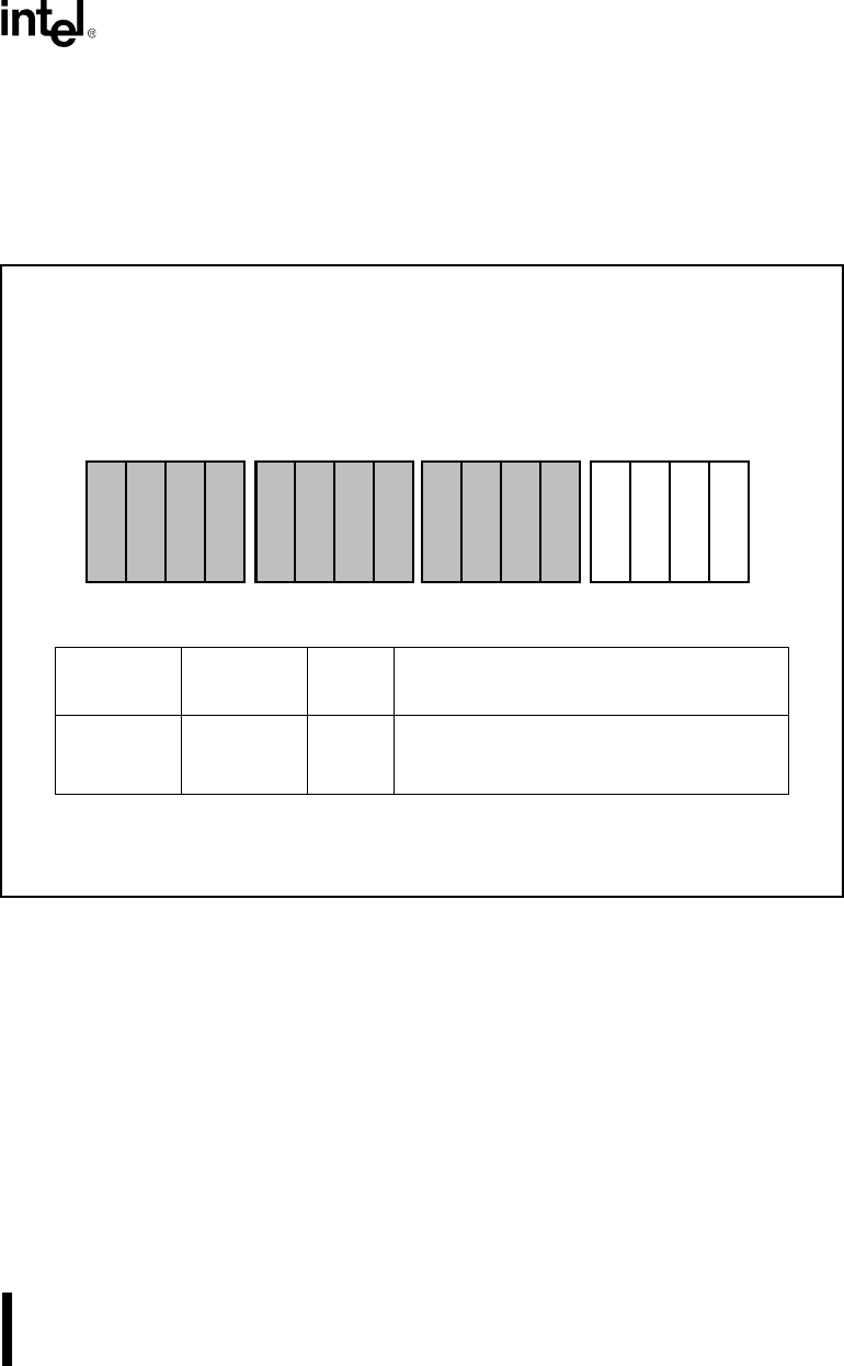
Figure 10-7. DMA Source Pointer (High-Order Bits)
Register Name: DMA Source Address Pointer (High)
Register Mnemonic: DxSRCH
Register Function: Contains the upper 4 bits of the DMA Source pointer.
Bit
Mnemonic
Bit Name
Reset
State
Function
DSA19:16 DMA
Source
Address
XXXXH DSA19:16 are driven on A19:16 during the
fetch phase of a DMA transfer.
NOTE: Reserved register bits are shown with gray shading. Reserved bits must be written
to a logic zero to ensure compatibility with future Intel products.
15 0
D
S
A
1
7
D
S
A
1
8
D
S
A
1
9
D
S
A
1
6
A1185-0A